Chapter: Digital Electronics : Synchronous and Asynchronous Sequential Circuits
Sequential Circuits Analysis Procedures
SEQUENTIAL CIRCUITS ANALYSIS PROCEDURES
This consists of obtaining a table or a diagram for the time sequence of inputs, outputs and internal states. Boolean expressions can also be written.
1. State Equations
A state equation specifies the next state as a function of the present state and inputs.
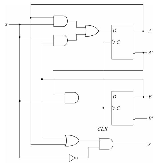
Consider the following sequential circuit:
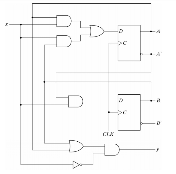
Since the D input of a flip-flop determines the value of the next state, the equations for the next state are:
A(t+1) = A(t) x(t) + B(t) x(t)
B(t+1) = A’(t) x(t)
The left-side of each equation denotes the next state of the flip-flop and the right-side specifies the present state and the conditions that make the next state equal to 1. These can be expressed in a more compact form by omitting the (t):
A(t+1) = Ax + Bx
B(t+1) = A’x
The present state value of the output can be expressed as:
y(t) =[A(t) + B(t)]x’(t)
The above output equation can be expressed in a more compact form as:
y = (A + B)x’
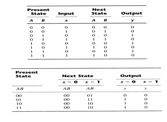
2. State Table
The time sequence of inputs, outputs, and flip-flop states can be enumerated in a state table. This can be generated from the logic diagram or the state equations.
Two alternative forms for the sequential circuit shown previously are as follows:
3. State Diagram
The information available in a state table can be represented graphically in a form of a state diagram. In this diagram, a state is represented by a circle, and the transitions between states by directed lines connecting the circles:
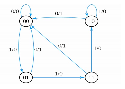
Each directed lines are labelled with two binary numbers separated by a slash. The input value during the present state is labelled first, and the number after the slash gives the output during the present state with the given input. A directed line connecting a circle with itself indicates that no change of state occurs.
4. Flip-Flop Input Equations
These fully specify the combinational logic that drives the flip-flops and they imply the type of flipflop from the letter symbol. The input equations for the circuit analysed before and shown below are:
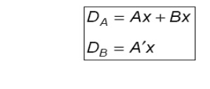
For a D flip-flop, the state equation is the same as the input equation. Input equations are sometimes called excitation equations.
Related Topics