Chapter: Satellite Communication : Space Segment and Satellite Link Design
Satellite uplink and downlink Analysis and Design
Satellite uplink
and downlink Analysis and Design:
1. Introduction
This
chapter describes how the link-power budget calculations are made.
These
calculations basically relate two quantities, the transmit power and the
receive power, and show in detail how the difference between these two powers
is accounted for.
Link-budget
calculations are usually made using decibel or decilog quantities. These are
explained in App. G. In this text [square] brackets are used to denote decibel
quantities using the basic power definition.
Where
no ambiguity arises regarding the units, the abbreviation dB is used. For
example, Boltzmann’s constant is given as 228.6 dB, although, strictly
speaking, this should be given as 228.6 deci logs relative to 1 J/K.
2. Equivalent
Isotropic Radiated Power
A
key parameter in link-budget calculations is the equivalent isotropic radiated
power, conventionally denoted as EIRP. From Eqs, the maximum power flux density
at some distance r from a transmitting antenna of gain G i

An
isotropic radiator with an input power equal to GPS would produce the same flux
density. Hence, this product is referred to as the EIRP, or EIRP is often
expressed in decibels relative to 1 W, or dBW. Let PS be in watts; then [EIRP]
= [PS] x [G] dB ,where [PS] is also in dBW and [G] is in dB.
3. Transmission
Losses
The
[EIRP] may be thought of as the power input to one end of the transmission
link, and the problem is to find the power received at the other end.
Losses
will occur along the way, some of which are constant.
Other
losses can only be estimated from statistical data, and some of these are
dependent on weather conditions, especially on rainfall.
The
first step in the calculations is to determine the losses for clear- weather or
clear-sky conditions. These calculations take into account the losses,
including those calculated on a statistical basis, which do not vary
significantly with time. Losses which are weather-related, and other losses
which fluctuate with time, are then allowed for by introducing appropriate fade
margins into the transmission equation.
Free-space transmission:
As
a first step in the loss calculations, the power loss resulting from the
spreading of the signal in space must be determined.
Feeder losses:
Losses
will occur in the connection between the receive antenna and the receiver
proper. Such losses will occur in the connecting waveguides, filters, and
couplers. These will be denoted by RFL, or [RFL] dB, for receiver feeder
losses.
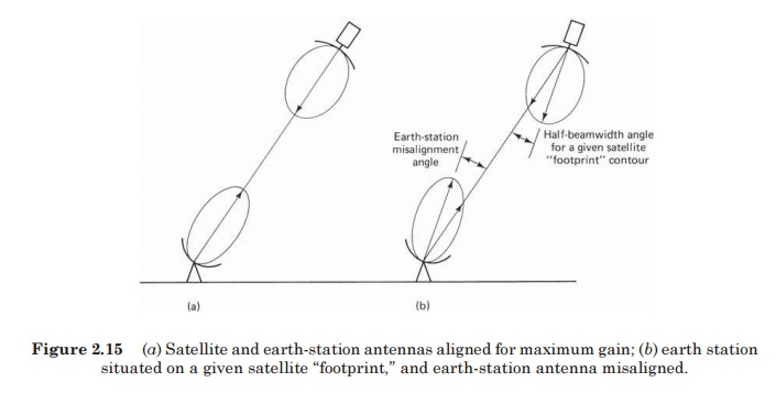
Antenna misalignment losses:
When
a satellite link is established, the ideal situation is to have the earth
station and satellite antennas aligned for maximum gain, as shown in Fig. There
are two possible sources of off-axis loss, one at the satellite and one at the
earth station, as shown in Fig.
The
off-axis loss at the satellite is taken into account by designing the link for
operation on the actual satellite antenna contour; this is described in more
detail in later sections. The off-axis loss at the earth station is referred to
as the antenna pointing loss. Antenna pointing losses are usually only a few
tenths of a decibel;
In
addition to pointing losses, losses may result at the antenna from misalignment
of the polarization direction (these are in addition to the polarization losses
described in Chap. 5). The polarization misalign- ment losses are usually
small, and it will be assumed that the antenna misalignment losses, denoted by
[AML], include both pointing and polar- ization losses resulting from antenna
misalignment. It should be noted
Related Topics