Chapter: Electrical machines : Electromechanical Energy Conversion and Concepts in Rotating Machines
Rotating Mmf Waves
Rotating Mmf Waves
The principle of operation of the induction machine is based on the generation of a rotating magnetic field. Let us understand this idea better.
Consider a cosine wave from 0 to 360◦. This sine wave is plotted with unit amplitude.
• Now allow the amplitude of the sine wave to vary with respect to time in a simisoidal fashion with a frequency of 50Hz.Let the maximum value of the amplitude is, say, 10 units. This waveform is a pulsating sine wave.
Now consider a second sine wave, which is displaced by 120◦ from the first (lagging).
• and allow its amplitude to vary in a similar manner, but with a 120◦time lag.Similarly consider a third sine wave, which is at 240◦ lag.
• and allow its amplitude to change as well with a 240◦ time lag. Now we have three pulsating sine waves.Let us see what happens if we sum up the values of these three sine waves at every angle.
The result really speaks about Tesla’s genius. What we get is a constant amplitude travelling sine wave!
In a three phase induction machine, there are three sets of windings,phase A winding, phase B and phase C windings. These are excited by a balanced three-phase voltage supply.
This would result in a balanced three phase current. Note that they have a 120◦ time lag between them.Further, in an induction machine, the windings are not all located in the same place.They are distributed in the machine 120◦ away from each other (more about this in the section on alternators). The correct terminology would be to say that the windings havetheir axes separated in space by 120◦. This is the reason for using the phase A, B and Csince waves separated in space as well by 120◦. When currents flow through the coils, they generate mmfs. Since mmf is proportional to current, these waveforms also represent the mmf generated by the coils and the total mmf.Further, due to magnetic material in the machine (iron), these mmfs generate magnetic flux,which is proportional to the mmf (we may assume that iron is infinitely permeable and non-linear effects such as hysterisis are neglected). Thus the waveforms seen above would also represent the flux generated within the machine. The net result as we have seen is a travelling flux wave. The x-axis would represent the space angle in the machine as one travels around the air gap. The first pulsating waveform seen earlier would then represent the a-phase flux, the second represents the b-phase flux and the third represents the c-phase.This may be better visualized in a polar plot. The angles of the polar plot represent the space angle in the machine, i.e., angle as one travels around the stator bore of the machine.
• This plot shows the pulsating wave at the zero degree axes. The amplitude is maximumat zero degree axes and is zero at 90◦ axis. Positive parts of the waveform are shown in red while negative in blue. Note that the waveform is pulsating at the 0−180◦ axis and red and blue alternate in any given side. This corresponds to the sinewave current changing polarity. Note that the maximum amplitude of the sinewave is reached only along the 0−180◦ axis. At all other angles, the amplitude does not reach a maximumof this value. It however reaches a maximum value which is less than that of the peak occuring at the 0 − 180◦ axis. More exactly, the maximum reached at any space angle would be equal to costimes the peak at the 0 − 180◦ axis. Further, at any space angle ,the time variation is sinusoidal with the frequency and phase lag being that of the excitation, and amplitude being that corresponding to the space angle.
• This plot shows the pulsating waveforms of all three cosines. Note that the first is pulsating about the 0 − 180◦ axis, the second about the120◦− 300◦axis and the thirdat 240◦− 360◦axis.
• This plot shows the travelling wave in a circular trajectory. Note that while individual pulsating waves have maximum amplitude of 10, the resultant has amplitude of 15. If f1 is the amplitude of the flux waveform in each phase.It is worthwhile pondering over the following points.
1. what is the interpretation of the pulsating plots of the animation? If one wants to know the ‘a’ phase flux at a particular angle for all instants of time, how can it be obtained?
2. What will this time variation look like? It is obviously periodic. What will be the amplitude and frequency?
1. Voltage induction caused by influence of rotating field
Voltage in three-phase windings revolving at variable speed, induced by a rotating field is subject to computation in the following:
Spatial integration of the air gap field results in the flux linkage of a coil. Induced voltage ensues by derivation of the flux linkage with respect to time. Using the definition of slip and a transfer onto three-phase windings, induced voltages in stator and rotor can be discussed. The following considerations are made only regarding the fundamental wave
2. Flux linkage
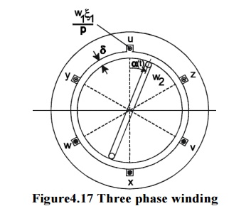
The air gap field is created in the three-phase winding of the stator, characterized by the number of windings w1 and current I1:
First of all, only one single rotor coil with number of windings w2 and arbitrary position angle of twistis taken into account. Flux linkage of the rotor coil results from spatial integration of the air gap flux density over one pole pitch.
3. Induced voltage, slip
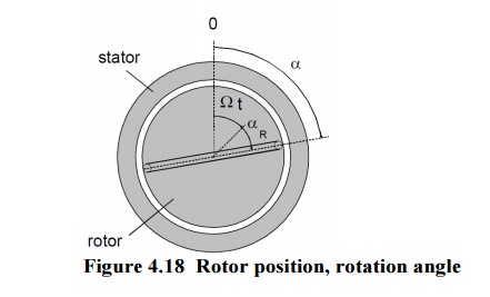
Induced voltage in a rotor coil of arbitrary angle of twist a(t), which is flowed through by the air gap flux density, computes from variation of the flux linkage with time.Described variation of flux linkage can be caused by both variation of currents iu(t), iv(t), iw(t)with time, inside the exciting three-phase winding and also by rotary motion a(t) of the coil along the air gap circumference.
· Some aspects regarding induced voltage dependencies are listed below: the amplitude of the induced voltage is proportional to the line frequency of the statorand to the according slip.
· frequency of induced voltage is equal to slip frequency at rotor standstill (s=1), frequency of the induced voltage is equal to line frequency.
· when rotating ( s < 1 ), voltage of different frequency is induced by the fundamental wave of the stator windings.
· no voltage is induced into the rotor at synchronous speed (s=0).
· phase displacement of voltages to be induced into the rotor is only dependent from thespatial position of the coil, represented by the (elec.) angle p R a .Is a rotor also equipped with a three-phase winding, instead of a single coil similar to thestator arrangement with phases being displaced by a mechanical angle, a number of slots per pole and phase greaterthan 1 (q>1) and the resulting number of windings w2;2 then follows for the induced voltage of single rotor phases.
Related Topics