Chapter: Electrical machines : Three Phase Induction Motor
Rotating Magnetic Field and Induced Voltages
Rotating Magnetic Field and
Induced Voltages
Consider
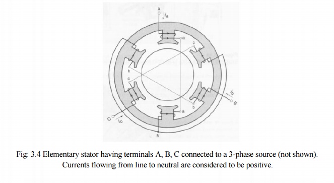
a simple stator having 6 salient poles, each of which carries a coil having 5
turns (Fig.3.4). Coils that are diametrically opposite are connected in series
by means of three jumpers that respectively connect terminals a-a, b-b, and
c-c. This creates three identical sets of windings AN, BN, CN, which are
mechanically spaced at 120 degrees to each other. The two coils in each winding
produce magneto motive forces that act in the same direction.
The three
sets of windings are connected in wye, thus forming a common neutral N. Owing
to the perfectly symmetrical arrangement, the line to neutral impedances are
identical. In other words, as regards terminals A, B, C, the windings
constitute a balanced 3-phase system.
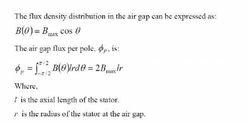
For a
two-pole machine, rotating in the air gap, the magnetic field (i.e., flux
density) being sinusoidally distributed with the peak along the centre of the
magnetic poles. The result is illustrated in Fig.3.5. The rotating field will
induce voltages in the phase coils aa', bb', and cc'. Expressions for the
induced voltages can be obtained by using Faraday laws of induction.
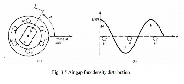
Let us
consider that the phase coils are full-pitch coils of N turns (the coil sides
of each phase are 180 electrical degrees apart as shown in Fig.3.5). It is
obvious that as the rotating field moves (or the magnetic poles rotate) the
flux linkage of a coil will vary. The flux linkage for coil aa' will be
maximum.
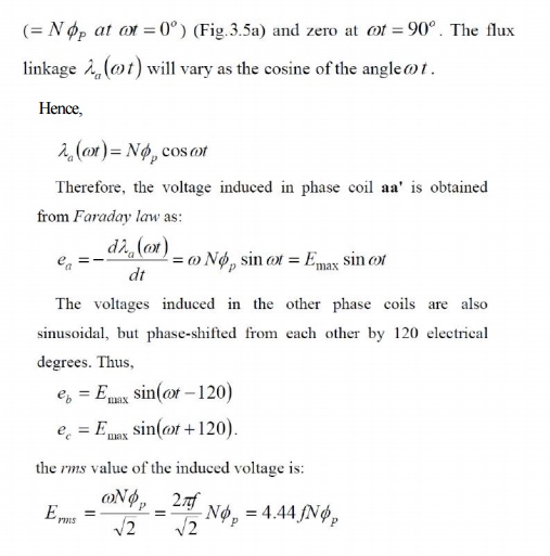
Where f
is the frequency in hertz. Above equation has the same form as that for the
induced voltage in transformers. However, ØP represents the flux per
pole of the machine.
The above
equation also shows the rms voltage per phase. The N is the total number of
series turns per phase with the turns forming a concentrated full-pitch
winding. In an actual AC machine each phase winding is distributed in a number
of slots for better use of the iron and copper and to improve the waveform. For
such a distributed winding, the EMF induced in various coils placed in
different slots are not in time phase, and therefore the phasor sum of the EMF
is less than their numerical sum when they are connected in series for the
phase winding. A reduction factor KW, called the winding factor,
must therefore be applied. For most three-phase machine windings KW
is about 0.85 to 0.95.
Therefore,
for a distributed phase winding, the rms voltage per phase is

Where Nph is the number of turns in
series per phase.
Related Topics