Chapter: Automation, Production Systems, and Computer Integrated Manufacturing : Industrial Robotics
Robot Programming
ROBOT
PROGRAMMING
To do
useful work, a robot must be programmed to perform its motion cycle. A robot program can be defined as a path in space 10 be followed by the
manipulator, combined with peripheral
actions that support the work cycle, Examples of the peripheral actions include
opening and closing the gripper, performing logical decision making, and
communicating with other pieces of equipment in the robot cell. A robot is
programmed by entering the
programming
commands into its controller memory. Different robots use different methods of
entering the commands
. In the
case of limited sequence robots, programming is accomplished by setting limit switches
and mechanical stops to control the endpoints of its motions. The sequence in
Lead through
Programming
Powered
Lead through Versus Manual Leadthrough. There are two methods of performing
the leadthrough teach procedure: (1) powered
leadthrough and (2) manual leadrhrough.
The
difference between the two is in the manner in which the manipulator is moved through the motion cycle
during programming. Powered leadthrough
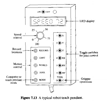
is commonly used a~ thc programming method for playback robots with point-to-point
control. It in· valves the use of J teach pendant (handheld control box) that
has toggle switches and/or contact buttons for controlling the movement of the
manipulator joints. Figure 7.13 illustrates the important components of a teach
pendant. Using the toggle switches or buttons, the programmer power drives the
robot arm to the desired positions, in sequence, and records the positions into
memory. During subsequent playback, the robot moves through the sequence 01
positions under its own power.
Manual
leadthrough is convenient for programming playback robots with
continuous path control where the continuous path is an irregular motion pattern
such as in spray painting. This programming method requires the operator to
physically grasp the end-of-arm or tool attached to the arm and manually move
it through the motion sequence, recording the path into memory. Because the
robot arm itself may have significant mass and would therefore he difficult to
move, a special programming device often replaces the actual robot for the
teach procedure. The programming device has the same joint configuration as the
robot. and it is equipped with a trigger handle (or other control switch),
which is activated when the operator wishes to record motions into memory. The
motions arc recorded a~ a series of closely spaced points' During playback, the
path is recreated by controlling the actual robot arm through the same sequence
of points.
Motion
Programming. The lendthrough methods provide a very natural way
of
programming
motion commands into the robot controller. In manual leadthrough, the operator
simply moves the arm through the required path to create the program. In
powered leadthrough the operator uses a teach pendant to drive the manipulator.
The teach pen b equipped with switch or a pair of contact buttons for each
joint By activating these switches or in a coordinated fashion for the various
joints. the programmer moves the manipulator to The required positions in the
work space.
Coordinating
the individual joints with the teach pendant is sometimes an awkward way to
enter motion commands to the robot, For example, it is difficult to coordinate
the individual joints of a jointed-arm robot (TRR configuration) to drive the
end-of-arm in a straight line motion. Therefore, many of the robots using
powered leadthrough provide two alternative methods for controlling movement of
the manipulator during programming, in addition to individual joint controls.
With these methods, the programmer can control the robot's wrist end to move in
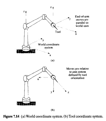
straight line paths. The names given to these alternatives are (1) world
coordinate system and (2) tool coordinate system. Both systems mak., use of a
Cartesian coordinate system. In/he world
coordinate system. the origin and frame of reference are defined with
respect to some fixed position and alignment relative to the robot base. This
arrangement is illustrated in Figure 7,14(a). In the tool coordinate system, shown in Figure 7 .14(b), the alignment of
the axis system is defined relative to the orientation of the wrist faceplate
(to which the end effector is attached). In this way, the programmer call
orient the tool in a desired way and then control the robot to make linear
moves in directions parallel OT perpendicular to the tool.
The world
coordinate system and the tool coordinate system are useful only if the robot
has the capacity to move its wrist end in a straight line motion, parallel to
one of the axes of the coordinate system. Straight line motion is quite natural
for a Cartesian coordinate robot (LOO configuration) but unnatural for robots
with any combination of rotational joints (types R, T, and V). To accomplish
straight line motion for manipulators with these types of joints requires a
linear interpolation process to be carried out by the robot's controller. In straight line interpolation. the control
computer calculates the sequence of addressable points in space that the wrist
end must move through to achieve a straight line path between two points.
There are
other types of interpolation that the robot can use. More common than straight
line interpolation is joint interpolation. When a robot is commanded to move
its wrist end between two points using joint
interpolation, it actuates each of the joints simultaneously at its own
constant speed such that all of the joints start and stop at the same time The
advantage of joint interpolation over straight line interpolation is that there
is usually less total motion energy required to make the move. This may mean
that the move could be made in slightly less time. It should be noted thai in
the case of a Cartesian coordinate robot, joint interpolation and straight line
interpolation result in the same motion path.
Still
another form of interpolation is that used in manual leadthrough programming In
this case, the robot must follow the sequence of closely space points that are
defined during the programming procedure. In effect, This is an interpolation
process for a path that usually consists of irregular smooth motions.
The speed
of the robot is controlled by means of a dial or other input device, located on
the teach pendant and/or tile main control panel. Certain motions in the work
cycle should be performed at high speeds (e.g., moving parts over substantial
distances in the work (ell), while other motions require low speed operation
(e.g. motions that require high precision in placing the workpart). Speed
control also permits a given program to be tried out at a safe slow speed and
then at a higher speed to be used during production.
There are
several inherent disadvantages of the lcadthrough programming methods. First,
regular production must he interrupted during the leadthrough programming
procedures. In other words, leadthrough programming results in downtime of the
robot cell or production line. The economic consequence of this is that the
lead through methods must be used for relatively long production runs and are
inappropriate for small batch sizes
Second.
the teach pendant used with powered leadthrough and the programming devices
used with manual leadthrough arc limited in terms of the decision-making logic
that can he incorporated into the program. It is much easier to write logical
instructions using the computer like robot languages than the lead through
methods
Third,
since the leadthrough methods were developed before computer control became
common for robots, these methods are not readily compatible with modem computer-based
technologies such as CAD/CAM, manufacturing data bases, and local
communications networks. The capability to readily interface the various
computer-automated subsystems in the factory for transfer of data is considered
a requirement for achieving computer integrated manufacturing.
Robot Programming languages
The use of
textual programming languages became an appropriate programming method as
digital computers took over the control function in robotics. Their use has
been stimulated by the increasing complexity of the tasks that robots are
called on to perform, with the concomitant need to imbed logical decisions into
the robot work cycle. These computer-like programming languages are really-online/off-fine
methods of programming, because the robot must still be taught its locations
using the leadthrough method. Textual programming languages for robots provide
the opportunity to perform the following functions that Ieadthrough programming
cannot readily accomplish:
enhanced
sensor capabilities. including the use of analog as well as digital inputs and
outputs
improved output
capabilities for controlling external
equipment
program logic that is beyond the capabilities of leadthrough methods
computations and data processing similar
to computer programming languages
communications with other
computer systems
This
section reviews some of the capabilities of the current generation robot
program ming languages. Many of the language statements are taken from actual
robot programming languages.
Motion
Programming. Motion programming with robot languages usually
requires a combination of textual statements and leadthrough techniques.
Accordingly, this method of programming is sometimes referred to as online/offline programming. The
MOVE PI
which
commands the robot to move from its current position to a position and
orientation defined by the variable name Pl. The point P1 must be defined, and
the most convenient way to define P1 is to use either powered leadthrough or
manual leadthrough to place the robot at the desired point and record that
point into memory. Statements such as
HERE PI
or
LEARN PI
are used
in the lcadthrough procedure to indicate the variable name for the point. What
is recorded into the robot's control memory is the set of joint positions or
coordinates used by the controller to define the point. For example, the
aggregate
(236.158,65.0.0,O)
could be
utilized to represent the joint positions for a six-jointed manipulator. The
first three values (236.158.65) give the joint positions of the body-and-arm,
and the last three values (0,0.0) define the wrist joint positions. The values
are specified in millimeters or degrees. Depending on the joint types.
There are
variants of the MOVE statement. These include the definition of straight line
interpolation motions, incremental moves, approach and depart moves, and paths.
For example, the statement
MOVES PI
denotes a
move that is to be made using straight line interpolation, The suffix S on MOVE
designates straight line motion.
An
incremental move is one whose endpoint is defined relative to the current
position of the manipulator rather than to the absolute coordinate system of
the robot. For example, suppose the robot is presently at a point defined by the
joint coordinates (236, 158, 65,0,O,0),and it is desired to move joint 4
(corresponding to a twisting motion of the wrist) from 0 to 125,The following
form of statement might be used to accomplish this move'
DMOVE (4, 125)
The new
joint coordinates of the robot would therefore be given by (236, 158, 65, 125, 0,
0). The prefix D is interpreted as delta, so DMOVE represents a delta move, or
incremental move.
Approach
and depart statements are useful in material handling operations. The APPROACH
statement moves the gripper from its current position 10 within a certain
distance
of the pickup
(or drop-off) point, and then a MOVE statement is used to position the end
effector at the pickup point. After the pickup is made. a DEPART statement IS
used to move the gripper away from the point. The following statements
illustrate the sequence:
APPROACH
P1,40 MM
MOVE PI
(actuate
gripper)
DEPART 40
MM
The final
destination is point Pl. but the APPROACH command moves the gripper to a safe
distance (40 mm) above the point. This might be useful to avoid obstacles such
as other parts in a tote pan. The orientation of the gripper at the end of the
APPROACH move is the same as that defined for the point PI, so that the final
MOVE Pi is really a spatial translation of the gripper. This permits the
gripper to be moved directly to the part
for
grasping.
A path in
a robot program is a series of points connected together in a single move. The
path is given a variable name, as illustrated in the following statement:
DEFINE PATHl23 = PATH(Pl.P2,P3)
This is a
path that consists of points PI. P2, and P3. The points are defined in the
manner described above. A MOVE statement is used to drive the robot
through the path.
MOVE PA.TH123
The speed
of the robot is controlled by defining either a relative velocity or an
absolute velocity. The following statement represents the case of relative
velocity definition:
SPEED 75
when this
statement appears within the pr ograrn, it is typically interpreted to mean
that the manipulator should operate at 75% of the initially commanded velocity
in the statements that follow in the program. The initial speed is given in a
command that precedes the execution of the robot program, For example,
SPEEDO.5MPS
EXECUTE PROGRAMI
indicates
that the program named PROGRAM} is to be executed by the robot, and rhar the
commanded speed during execution should he 0.5 m/sec.
Interlock
and Sensor Commands. The two basic interlock commands (Section 4.3.2)
used for industrial robots are WAIT and SIGNAL. The WAIT command is used to
implement an input interlock. For example,
WAIT20,ON
would
cause program execution to stop at this statement until the input signal coming
into the robot controller at port 20 was in an "on" condition. This
might be used to cause the robot to want for the completion of an automatic
machine cycle in a loading and unloading application.
The
SIGNAL statement is used to
implement an output interlock. This is used to communicate to some external piece of equipment. For example,
SIGNAL 10. ON
would
switch on the signal at output port 10, perhaps to actuate the start of an
automatic machine cycle.
Both of
the above examples indicate on/off signals. Some robot controllers possess the
capacity to control analog device, that operate at various levels. Suppose it
were desired to turn on an external device that operates on variable voltages
in the range 0 to 10 V. The command
SIGNAL 10,6.0
is
typical of a control statement that might be used to output a voltage level of 6.0
V to the device from controller output port 10.
All of
the above interlock commands represent situations where the execution of the
statement occurs at the point in the program where the statement appears. There
are other situations in which it is desirable for an external device to be
continuously monitored for any change that might occur in the device, This
might be useful, for example, in safety monitoring where a sensor is set up to
detect the presence of humans who might wander into the robot's work volume.
The sensor reacts to the presence of the humans by signaling the robot controller. The following type of statement might
he used for this case:
REACT 25. SAFESTOP
This
command would be written to continuously monitor input port 25 for any changes
in the incoming signal. If aud when a change in the signal occurs, regular
program execution is interrupted, and control is transferred to a subroutine
called SAFESTOP. This subroutine would stop the robot from further motion
and/or cause some other safety action to be taken.
End effectors
arc devices that, although they are attached to the wrist of the manipulator.
are actuated very much like external devices. Special commands are usually
written for controlling the end effector. In the case of grippers, the basic
commands are
OPEN
and
CLOSE
which
came the gripper to actuate to fully open and fully closed positions,
respectively. Greater control over the gripper is available in some sensored
and servo-controlled hands.
For
grippers that have force sensors that can be regulated through the robot
controller, a command such as
CLOSE2.0N
controls
the dosing of the gripper until a 2.0N force is encountered by the gripper fingers. A similar
command used \0 close the gripper to a given opening width is:
CLOSE25MM
A special
set of statements is often required to control the operation of tool-type end
effectors, such as spot welding guns, arc welding tools, spray painting guns,
and powered spindles (for drilling, grinding, etc.]. Spot welding and spray
painting controls are typically simple binary commands (e.g., open/close and
on/off), and these commands would be similar to those used for gripper control.
In the case of arc welding and powered spindles, a greater variety of control
statements is needed to control feed rates and other parameters of the
operation
Computations
and Program Logic. Many of the current generation robot languages
possess capabilities for performing computations and data processing operations
that are similar to computer programming languages. Most present-day robot
applications do not require a high level of computational power. As the
complexity of robot applications grows in the future, it is expected that these
capabilities will be better utilized than at present,
Many of
today's applications of robots require the use of branches and subroutines in
the program. Statements such as
GOTO 150
and
IF
(logical expression) GO TO 150
cause
tile program TO branch to some other statement in the program [e.g., to
statement number 150 in the above illustrations).
A
subroutine in a robot program is a group of statements that are to be executed
separately when called from the main program. In a preceding example, the
subroutine SAFESTOP was named in the REACT statement for use in safety
monitoring. Other uses of subroutines include mak.ing calculations or
performing repetitive motion sequences at a number of different places in the
program. Rather than write the same steps several times in the program, The use
of a subroutine is more efficient.
Simulation and Offline
Programming
The
trouble with leadthrough methods and textual programming techniques is that the
robot must be ta.ken out of production for a certain length of time to
accomplish the programming. Off-line programming permits the robot program to be prepared at a remote computer
terminal and downloaded to the robot controller for execution. In true offline programming.
there is no need to physically locate the positions in the workspace for the
robot as required with present textual programming languages. Some form of
graphical computer simulation is required to validate the programs developed
offline, similar to offline procedures used in NC part programming. The
advantage of true offline programming is that new programs can be prepared and
downloaded to the robot without interrupting production
The off-line
programming procedures being developed and commercially offered use graphical
simulation to construct a three-dimensional model of a robot cell for
evaluation and offline programming. The cell might consist of the robot,
machine tools, conveyors, and other hardware. The simulator permits these cell
components to be displayed on the graphic, monitor and for the robot to perform
its work cycle in animated computer graphics. After the program has been
developed using the simulation procedure, it is then converted into the textual
Language corresponding to the particular robot employed in the cell. This is a
step in the offline programming procedure that is equivalent to post-processing
in NC part programming.
In the
current commercial offline programming packages, some adjustment must be
performed to account for geometric differences between the three-dimensional
model in the computer system and the actual physical cell. For example, the
position of a machine tool in the physical layout might be slightly different
than in the model used to do the off-line programming. For the robot to
reliably load and unload the machine, it must have an accurate location of the
load/unload point recorded in its control memory. This module is used to
calibrate the 3D computer model by substituting location data from the actual
cell for the approximate values developed in the original model. The
disadvantage with calibrating the cell is that time is lost in performing this
procedure.
In future
programming systems, the offline procedure described above will probably be
augmented hy means of machine vision and other sensors located in the cell. The
vision and sensor systems would be used to update the three-dimensional model
of the workplace and thus avoid the necessity for the calibration step in
current offline programming methods. The term sometimes used 10 describe these
future programming systems in which the robot possesses accurate knowledge of
its three-dimensional workplace is world
modeling. Associated with. the concept of world modeling is the use of very
high-level language statements, in
which the programmer specifies a task to be done without giving details of the
procedure used to perform the tusk. Examples of this type of statement might be
ASSEMBLE PRINTING MECHANISM TO BRACKET
or
WELD UPPER PLATE TO LOWER PLATE
The
statements are void of any reference to points in space or motion paths to be
followed by the robot. Instead, the three-dimensional model residing in the
robot's control memory would identify the locations of the various items to be
assembled or welded. The future robot would possess sufficient intelligence to
figure out its own sequence of motions and actions for performing the task
indicated.
Related Topics