Chapter: Civil : Water Resources and Irrigation Engineering : Diversion and Impounding Structures
River Training: Design Parameters
DESIGN PARAMETERS
1.Waterway
Waterway
or length of the work (L) is adopted as given by Lacey’ viz. 83 Q1/2.
It is termed as active waterway. An additional span is generally provided to
make
up for the loss of waterway in end
spans which are partially obstructed by the training works or khadir In railway
practice, less twice the width of pierfoundation wells. Overall waterway, L, be
guide banks is usually taken as 1.1 to 1.25 L ascertain the waterway required.
2.Length of Guide Bank
The two
important consideration for determining the length of guide banks for wide
alluvial rivers are (i) Maximum obliquity of the current. In order to avoid
heavy river action on the guide bank, the obliquity of flow to the river axis
is limited to not more than 300, and (ii) Permissible limit to which
the main river channel can be allowed to flow near the approach embankment in
the event of the river developing excessive embayment behind the training
works. The radius of the worst possible loop is ascertained from the data of
the active loops formed by the river.
(a)
The
upstream length of guide bank is normally kept 1.0 to 1.5 as per IS: 84081976.
Spring recommended length 1.1 L and Gales 1.25 L for Q up to 20,000 cumecs and
1.50 L for Q above 20,000 cumecs.
Downstream length. The river fans out on downstream of the work to attain its normal width. The function of downstream length of guide bank is to ensure that in fanning out the river does not threaten the approach embankments on either side of the work or afflux bunds or canal embankments. A short guide bank with sharp curved head is considered suitable for the purpose. The downstream length of guide banks is usually kept 0.25 L to 0.4 L as per I.S. 84081976. Spring recommended 0.1 to 0.2 L, and Gales 0.25 L.
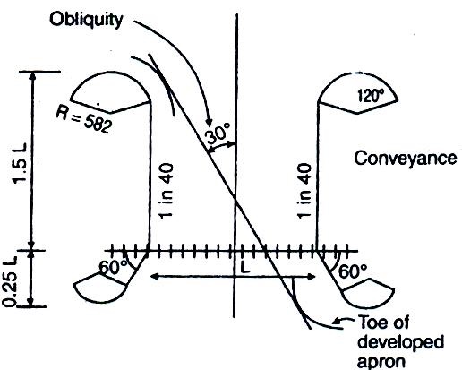
Figure: Gale’s pattern
3.
Curved
Head and Tail
(a) Circular head. The upstream curved
head is designed to guide the flow smoothly and axially to the structures to
keep the end spans effective and active.
Upstream
head. The upstream curved portion of the guide bank, termed as impregnable
head, is provided with a suitable curvature usually of a radius as small as
possible consistent with proper functioning of the guide bank. Unless indicated
by model studies, the minimum and maximum embankment with a minimum cover of
0.9 m. The seepage gradient in accordance with the nature of soil varies from
4: 1 to 6:1.
Salient parameters of cross section f
embankment are given in Table 9.3.
Table : Salient parameters of crosssection
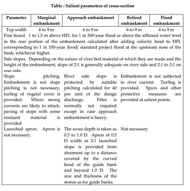
Parameter Marginal
embankment Approach embankment Retired embankment Flood embankment
Top width 6 to 9 m 6 to 9 m 6 to 9 m 6
to 9 m
Free board. 1 to 1.5 m above HFL
for 1 in 500year flood or above the affluxed water level in the rear portion of
the embankment calculated after adding velocity head to HFL corresponding to 1
in 100year flood/ standard project flood at the upstream nose of the bank,
whichever higher.
Side slopes. Depending on the
nature of river bed material of which they are made and the height of the
embankment, slope of 2:1 is generally adequate on river side and 2:1 to 3:1 on
rear side.
a.Slope pitching. Embankment is not slope
pitching is not necessary,
turfing of vegetal
cover is provided. Where strong currents are likely to attack, paving
of slope with
some resistant material is provided
b.River side slope is protected by suitable pitching calculated for 40 per
cent of the
design discharge. Filter is
normally not required except in case approach embankment is heavy.
c.Embankment is not subjected to
river current. Turfing
is provided. Spurs and other
protective measures are provided at salient points.
a.Launched apron. not necessary.
c.not necessary
Embankment Failure
Factors
responsible for embankment failure are (i) Erosion of river side by wave wash
during very strong current, (ii) Sloughing of the bank slope when saturated with
water by floods of long duration, (iii) Sloughing of inland side slope caused
by under seepage, (iv) Piping in sublayers due to movement of ground water
towards the river, which carries away material with it. Gradual reduction of
crosssection of the embankment takes place due to gradual removal of the
embankment material with it. Gradual reduction of cross section of the
embankment takes place
due to gradual removal of the
embankment material through the joints or interstices of the protection
movement, (v) Toe of the bank undermined by eddies, currents, etc. followed by
a collapse of overhanging material deprived of support, (vi) Overtopping due to
a flood of a magnitude greater than the design flood, (vii) Insufficient cross
section, leaks and cracks due to shrinkage of soil and ratholes while breaches
could result from overtopping of an embankment due to higher than design flood
levels being obtained in a river as also due to river erosion. One of the
important causes usually is lack of proper maintenance by way not only of
annual repairs, but also inadequacy or slackness in watch and timely action
during the flood season.
Related Topics