Chapter: Civil : Foundation Engineering : Retaining Walls
Retaining Walls

RETAINING WALLS
RETAINING WALL
Retaining walls are
structures used to retain earth or water or other materials such as coal, ore,
etc; where conditions do not permit the mass to assume its natural slope. The
retaining material is usually termed as backfill. The main function of
retaining walls is to stabilize hillsides and control erosion. When roadway
construction is necessary over rugged terrain with steep slopes, retaining
walls can help to reduce the grades of roads and the land alongside the road.
Some road projects lack available land beside the travel way, requiring
construction right along the toe of a slope. In these cases extensive grading
may not be possible and retaining walls become necessary to allow for safe
construction and acceptable slope conditions for adjacent land uses. Where
soils are unstable, slopes are quite steep, or heavy runoff is present, retaining
walls help to stem erosion. Excessive runoff can undermine roadways and
structures, and controlling sediment runoff is a major environmental and water
quality consideration in road and bridge projects. In these situations,
building retaining walls, rather than grading excessively, reduces vegetation
removal and reduces erosion caused by runoff. In turn, the vegetation serves to
stabilize the soil and filter out sediments and pollutants before they enter
the water source, thus improving water quality.
In
this section you will learn the following
Gravity
walls
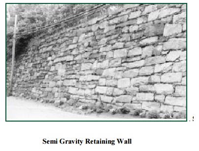
Semi
Gravity Retaining Wall
Flexible
walls
Special type of retaining walls
Different Types of
Retaining Structures On the basis of attaining stability, the
retaining structures are classified into following: 1. Gravity walls
:
Gravity
walls are stabilized by their mass. They are constructed of dense, heavy
materials such as concrete and stone masonry and are usually reinforced. Some
gravity walls do use mortar, relying solely on their weight to stay in place,
as in the case of dry stone walls. They are economical for only small heights.
These
walls generally are trapezoidal in section. This type of wall is constructed in
concrete and derives its stability from its weight. A small amount of
reinforcement is provided for reducing the mass of the concrete.This can be
classified into two:
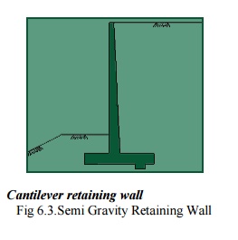
Fig
6.3.Semi Gravity Retaining Wall
Cantilever retaining wall
Counter
fort retaining wall Cantilever
retaining wall
This is a reinforced concrete wall which utilises
cantilever action to retain the backfill. This type is suitable for
retaining backfill to
moderate heights(4m-7m). In cross section most canti 'T's. To ensure stability,
they are built on soli with reinforcement rods. The base is then backfilled to
counteract forward pressure on the vertical portion of the
wall. The cantilevered
base is reinforced and is designed to prevent uplifting at the heel of the
base, making the wall strong and stable. Local building codes, frost
penetration levels and soil qualities determine the foundation and structural
requirements of taller cantilevered walls. Reinforced concrete cantilevered
walls sometimes have a batter. They can be faced with stone, brick, or
simulated veneers. Their front faces can also be surfaced with a variety of
textures. Reinforced Concrete Cantilevered Walls are built using forms. When
the use of forms is not desired, Reinforced Concrete Block Cantilevered Walls
are another option. Where foundation soils are poor, Earth Tieback Retaining
Walls are another choice. These walls are counterbalanced not only by a large
base but also by a series of horizontal bars or strips extending out
perpendicularly from the vertical surface into the slope. The bars or strips,
sometimesadmen'calledare'demade
of wood, metal, or synth tieback retaining wall is backfilled, the weight and
friction of the fill against the horizontal members anchors the structure.
Counterfort retaining wall
When
the height of the cantilever retaining wall is more than about 7m, it is
economical to provide vertical bracing system known as counter forts. In this
case, both base slab and face of wall span horizontally between the counter
forts.
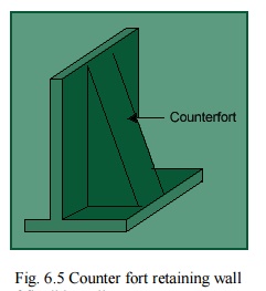
Fig.
6.5 Counter fort retaining wall
3.
Flexible walls: there are two classes of flexible walls.
Sheet pile walls and
Diaphragm wall A. Sheet Pile Walls Sheet piles are generally made of steel or timber. The use of timber piles is generally limited to temporary sdtructures in which the depth of driving does not exceed 3m. for permanent structures and for depth of driving greater than 3m, steel piles are most suitable. Moreover, steel iles are relatively water tight and can be extracted if required and reused. However, the cost of sheet steel piles is generally more than that of timber piles. Reinforced cement concrete piles are generally used when these are to be jetted into fine sand or driven in very soft soils, such as peat. For tougher soils , the concrete piles generally break off. Based on its structural form and loading system, sheet pile walls can be classified into 2 types:(i)Cantilever Sheet Piles and(ii)Anchored Sheet Piles
1. Cantilever
sheet pile walls:
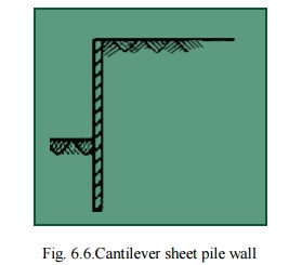
Fig. 6.6.Cantilever sheet pile wall
Cantilever sheet piles are further divide into two types:
![]() Free cantilever sheet pile It is a sheet pile
subjected to a concentrated horizontal load at its top. There is no back fill
above the dredge level. The free cantilever sheet pile derives its stability
entirely from the lateral passive resistance of the soil below the dredge level
into which it is driven.
Free cantilever sheet pile It is a sheet pile
subjected to a concentrated horizontal load at its top. There is no back fill
above the dredge level. The free cantilever sheet pile derives its stability
entirely from the lateral passive resistance of the soil below the dredge level
into which it is driven.
Cantilever Sheet Pile Wall with Backfill
A
cantilever sheet pile retains backfill at a higher level on one side. The
stability is entirely from the lateral passive resistance of the soil into
which the sheet pile is driven, like that of a free cantilever sheet pile.
2.
Anchored sheet pile walls Anchored shet pile walls are held above the
driven depth by anchors provided ata suitable level. The anchors provided for
the stability of the sheet ile , in addition tomthe lateral passive resistance
of the soil into which the shet piles are driven. The anchored sheet piles are
also of two types.
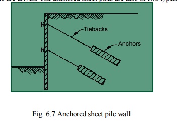
Free earth
support piles. An anchored pile is said to have free
earth support when the depth of embedment is small and the pile rotates
at its bottom tip. Thus there is a point of contraflexure in the pile. ![]() Fixed earth support piles. An
anchored sheet pile has fixed earth support when the depth of embedment is
large. The bottom tip of the pile is fixed against rotations. There is a
change in the curvature of the pile, and hence, an inflection point
Fixed earth support piles. An
anchored sheet pile has fixed earth support when the depth of embedment is
large. The bottom tip of the pile is fixed against rotations. There is a
change in the curvature of the pile, and hence, an inflection point
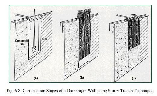
occurs. Diaphragm
Walls Diaphragm walls are commonly used in congested areas for retention
systems and permanent foundation walls. They can be installed in close
proximity to existing structures, with minimal loss of support to existing
foundations. In addition, construction dewatering is not required, so there is
no associated subsidence. Diaphragm walls have also been used as deep
groundwater barriers through and under dams.
Diaphragm
walls are constructed by the slurry trench technique which was developed in
Europe, and has been used in the United States since the l940's. The technique
involves excavating a narrow trench that is kept full of an engineered fluid or
slurry. The slurry exerts hydraulic pressure against the trench walls and acts
as shoring to prevent collapse. Slurry trench excavations can be performed in
all types of soil, even below the ground water table. Cast in place; diaphragm
walls are usually excavated under bentonite slurry. The construction sequence
usually begins with the excavation of discontinuous primary panels. Stop-end
pipes are placed vertically in each end of the primary panels, to form joints
for adjacent secondary panels. Panels are usually 8 to 20 feet long, with
widths varying from 2 to 5 feet. Once the excavation of a panel is complete, a
steel reinforcement cage is placed in the center of the panel. Concrete is then
poured in one continuous operation, through one or several tremie pipes that extend
to the bottom of the trench. The tremie pipes are extracted as the concrete
raises in the trench, however the discharge of the tremie pipe always remains
embedded in the fresh concrete. The slurry, which is displaced by the concrete,
is saved and reused for subsequent panel excavations. When the concrete sets,
the end pipes are withdrawn. Similarly, secondary panels are constructed
between the primary panels, and the process continues to create a continuous
wall. The finished walls may cantilever or require anchors or props for lateral
support.
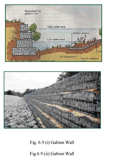
4. Special
type of retaining walls Gabion walls
Gabion walls are
constructed by stacking and tying wire cages filled with trap rock or native
stone on top of one another. They can have a continuous batter (gently sloping)
or be stepped back (terraced) with each successively higher course.
This
is a good application where the retaining wall needs to allow high amounts of
water to pass through it, as in the case of riverbank stabilization. It is
important to use a filter fabric with the gabion to keep adjacent soil from
flowing into or through the cages along with the water. As relatively flexible
structures, they are useful in situations where movement might be anticipated.
Vegetation can be re-established around the gabions and can soften the visible
edges allowing them to blend into the surrounding landscape. For local roads, they
are a preferred low-cost retaining structure.
Design
Requirement for Gravity walls
Gravity Retaining walls
are designed to resist earth pressure by their weight. They are constructed of
the mass, concrete, brick or stone masonry. Since these materials can not
resist appreciable tension, the design aims at preventing tension in the wall. The
wall must be safe against sliding and overturning. Also the maximum pressure
exerted on the foundation soil should exceed the safe bearing capacity of the
soil.
So before the actual
design, the soil parameters that influence the earth pressure and the bearing
capacity of the soil must be evaluated. These include the unit weight of the
soil, the angle of the shearing resistance, the cohesion intercept and the
angle of wall friction. Knowing these parameters, the lateral earth pressure
and bearing capacity of the soil determined.
Design Requirement for Gravity walls
Gravity Retaining walls
are designed to resist earth pressure by their weight. They are constructed of
the mass, concrete, brick or stone masonry. Since these materials can not
resist appreciable tension, the design aims at preventing tension in the wall.
The wall must be safe against sliding and overturning. Also the maximum
pressure exerted on the foundation soil should exceed the safe bearing capacity
of the soil.
So
before the actual design, the soil parameters that influence the earth pressure
and the bearing capacity of the soil must be evaluated. These include the unit
weight of the soil, the angle of the shearing resistance, the cohesion
intercept and the angle of wall friction. Knowing these parameters, the lateral
earth pressure and bearing capacity of the soil determined.
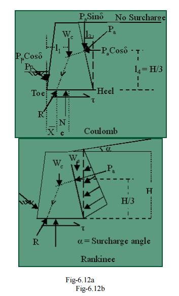
Fig.
6.12a shows a typical trapezoidal section of a gravity retaining wall.
The forces acting on the wall per unit length are:
�
Active Earth pressure Pa .
�
The weight of the wall Wc
�
The Resultant soil reaction R on the
base. (or Resultant of weight Wc & Pa).Strike the base at point D. There is
equal and opposite reaction R' at the base between the wall and the foundation.
�
Passive earth pressure Pp acting on the lower portion of the face of
the wall, which usually small and usually neglected for design purposes. The
full mobilization of passive earth pressure not occurs at the time of failure
so we not consider it. If we consider it then it shows resistance against
instability. So if we ignore it then we will be in safer side.
First decide which
theory we want to apply for calculating the active earth pressure. Normally we
calculate earth pressure using Rankine's theory or Coulomb's Earth pressure
theory.
For using Rankine's theory, a vertical line AB is
drawn through the heel point
( Fig 6.12-b ). It is
assumed that the Rankine active condition exist along the vertical line AB.
While checking the stability, the weight of the soil ( Ws) above the heel in the zone ABC should also be taken in to
consideration, in
addition to the Earth pressure ( Pa and weight of the wall ( Wc).
But Coulomb's theory gives directly the lateral
pressure ( Pa) on the back face of the
wall, the forces to be
considered only Pa (Coulomb) and the Weight of the wall ( Wc ). In this case, the weight of soil ( Ws ) is need not be considered.
Once the forces acting
on the wall have been determined, the Stability is checked using the procedure
discussed in the proceeding section. For convenience, the section of the
retaining wall is divided in to rectangles & triangles for the computation
of the Weight and the determination of the line of action of the Weight.
For
a safe design, the following requirement must be satisfied.
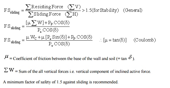
No Sliding
Horizontal
forces tend to slide the wall away from the fill. This tendency is resisted by
friction at the base.
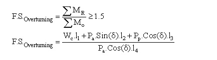
No Overturning
The
wall must be safe against overturning about toe.
No
Bearing Capacity Failure and No Tension
First calculate the line of action of the Resultant
force ( e ) from centre of the base.
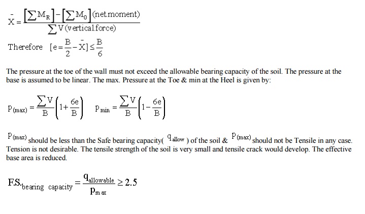
(No
Tension will develop at the heel)
The
pressure at the toe of the wall must not exceed the allowable bearing capacity
of the soil. The pressure at the base is assumed to be linear. The max.
Pressure at the Toe & min at the Heel is given by:
P(max) should
be less than the Safe bearing capacity( P allow )
of the soil & P max should
not be Tensile in any case. Tension is not desirable. The tensile strength of
the soil is very small and tensile crack would develop. The effective base area
is reduced.
Related Topics