Phasor diagram, Circuit Diagram, Formula | Alternating Current (AC) - Resonance in series RLC Circuit | 12th Physics : Electromagnetic Induction and Alternating Current
Chapter: 12th Physics : Electromagnetic Induction and Alternating Current
Resonance in series RLC Circuit
Resonance in series RLC Circuit
When the frequency of
the applied alternating source (
Žēr ) is equal to the natural
frequency
| 1/ ŌłÜ(LC) | of the RLC circuit, the current in the
circuit reaches its maximum value. Then the circuit is said to be in electrical
resonance. The frequency at which resonance takes place is called resonant
frequency.
Resonant angular
frequency, Žēr = 1/ ŌłÜ(LC)
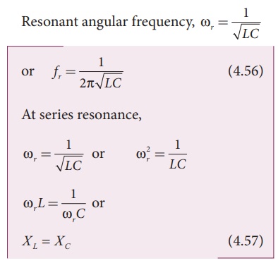
Since XL
and XC are frequency dependent, the resonance condition ( X L
= XC ) can be achieved by the
varying the frequency of the applied voltage.
Effects of series resonance
When series resonance
occurs, the impedance of the circuit is minimum and is equal to the resistance
of the circuit. As a result of this, the current in the circuit becomes
maximum. This is shown in the resonance curve drawn between current and
frequency (Figure 4.54).
At resonance, the
impedance is
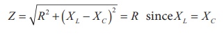
Therefore, the current
in the circuit is
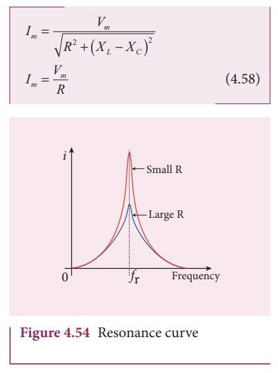
The maximum current at
series resonance is limited by the resistance of the circuit. For smaller
resistance, larger current with sharper curve is obtained and vice versa.
Applications of series RLC resonant circuit
RLC circuits have many
applications like filter circuits, oscillators, voltage multipliers etc. An
important use of series RLC resonant circuits is in the tuning circuits of
radio and TV systems. The signals from many broadcasting stations at different
frequencies are available in the air. To receive the signal of a particular
station, tuning is done.
The tuning is commonly
achieved by varying capacitance of a parallel plate variable capacitor, thereby
changing the resonant frequency of the circuit. When resonant frequency is
nearly equal to the frequency of the signal of the particular station, the
amplitude of the current in the circuit is maximum. Thus the signal of that
station alone is received.
Related Topics