Chapter: Aquaculture Engineering : Water Transport
Regulation of flow from selected pumps
Regulation of flow from selected pumps
In many cases there is a requirement to adjust the water flow from specific pumps, for instance to reduce it. It is possible to use several methods for this purpose and these are briefly described below.
Adjustment of RPM
One method for regulating the water flow from a pump is to change the speed (RPM) of the motor and hence the impeller. When the speed is dimin-ished both the water flow and the head are reduced. The usual type of electric motor employed for pumps is an asynchronous motor. Its speed may be changed by coupling in and out extra sets of poles in steps by a switch, which will change the RPM of the motor, also in steps. The following connection is given between the RPM (n), water flow (Q), head (H) and the power (P):
Q2/Q1= n2/n1
H2/H1=(n2/n1)2
P2/P1=(n2/n1)3
From these equations it can be seen that the water flow increases in direct proportion to the RPM, the head increases in proportion to the square of the RPM, and the power increases in proportion to the cube of the RPM.
Continuous adjustment of the RPM in pumps is, however, difficult in practice. The motor on a cen-trifugal pump normally uses alternating current and the continuous adjustment of a.c. motors is quite complicated and expensive. The usual way to adjust the motor speed is to transform the frequency of the current (Fig. 2.21). If, for instance, the normal frequency of the electricity is 50 Hz, reducing it to 40 Hz will reduce the speed of the motor, which will reduce the water flow out of the pump but main-tain the head. Reducing the a.c. frequency can affect the pump motor; if it is reduced too much, the motor will stop and may be destroyed. The same thing can happen if the frequency is increased to above 50 Hz.
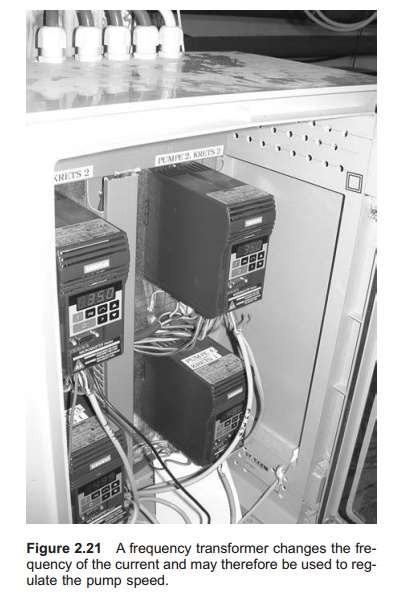
The disadvantage of this system is that frequency regulators are quite expensive and some energy loss occurs during frequency transformation. Large improvement have, however, been made in the technology in this field during the past few years, and the cost has been considerably reduced.
Example
A pump delivers 300 l/s. The speed of the pump motor must be changed so that the pump only delivers 200 l/s. The original speed of the pump is 2800 RPM/ min. What is the new speed? The power supply is 30 kW at the start. What is the new power supply?
The new RPM is going to be:
Q2/ Q1= n2/n1
n2= Q2n1/Q1
=200 × 2800/300
=1867 RPM
The new power supply will be:
P2/ P1=(n2/n1)3
P2= P1(n2/n1)3
=30(200/300)3
=8.9 kW
Throttling
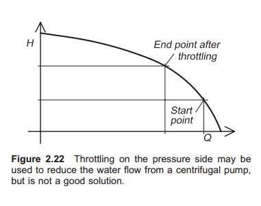
By placing a throttle valve on the pressure side, it is possible to close the outlet of the pump (throttle) (Fig. 2.22). In this way an artificial head is created and hence a reduction in the water flow, according to the pump characteristics. Higher throt-tling results in a move to the left on the pump curve. To throttle on the pressure side is only possible for centrifugal pumps, because the water is inhibited from going to the peripheries of the impeller. Throttling on the pressure side on pump types other than centrifugal and propeller can result in pump break-age. Throttling centrifugal and propeller pumps is not very satisfactory as there is significant energy loss because the throttling valve creates an artificial head. The power consumption is the same when the water flow is reduced, which easily can be seen from the left shift on the characteristics curve. To throttle a centrifugal pump on the suction inlet must be avoided as this easily creates cavitation conditions in the pump.
Several pumps
If there are large water requirements and the dis-charge varies, it is an advantage to use several pumps of different sizes. In this way it is possible to couple pumps in and out and by doing this vary the total flow rate (parallel connection) and at the same time achieve an overall high efficiency for all the running pumps. To use several pumps will also improve the reliability because one pump can stop without halting the total water flow to a farm.
Related Topics