Chapter: Optical Communication and Networking : Introduction
Ray theory transmission
Ray theory transmission
1. Total internal reflection
To consider the propagation of light within an optical fiber utilizing the ray theory model it is necessary to take account of the refractive index of the dielectric medium. The refractive index of a medium is defined as the ratio of the velocity of light in a vacuum to the velocity of light in the medium.
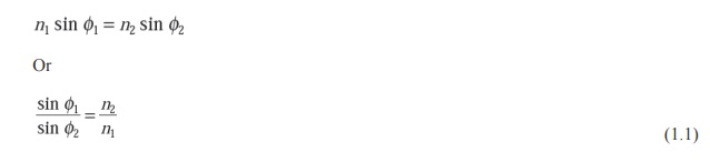
A ray of light travels more slowly in an optically dense medium than in one that is less dense, and the refractive index gives a measure of this effect. When a ray is incident on the interface between two dielectrics of differing refractive indices (e.g. glass–air), refraction occurs, as illustrated in Figure 1.2(a). It may be observed that the ray approaching the interface is propagating in a dielectric of refractive index n and is at an angle φ to the normal at the surface of the interface. If the dielectric on the other side of the interface has a refractive index nwhich is less than n1, then the refraction is such that the ray path in this lower index medium is at an angle to the normal, where is greater than . The angles of incidence and refraction are related to each other and to the refractive indices of the dielectrics by Snell’s law of refraction, which states that:
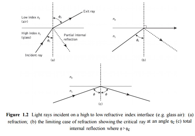
It may also be observed in Figure 1.2(a) that a small amount of light is reflected back into the originating dielectric medium (partial internal reflection). As nis greater than n, the angle of refraction is always greater than the angle of incidence. Thus when the angle of refraction is 90° and the refracted ray emerges parallel to the interface between the dielectrics, the angle of incidence must be less than 90°. This is the limiting case of refraction and the angle of incidence is now known as the critical angle φc, as shown in Figure 1.2(b). From Eq. (1.1) the value of the critical angle is given by
At angles of incidence greater than the critical angle the light is reflected back into the originating dielectric medium (total internal reflection) with high efficiency (around 99.9%). Hence, it may be observed in Figure 1.2(c) that total internal reflection occurs at the inter- face between two dielectrics of differing refractive indices when light is incident on the dielectric of lower index from the dielectric of higher index, and the angle of incidence of the ray exceeds the critical value. This is the mechanism by which light at a sufficiently shallow angle (less than 90° − may be considered to propagate down an optical fiber with low loss.
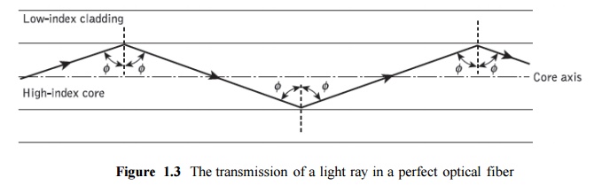
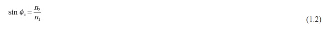
Figure 1.3 illustrates the transmission of a light ray in an optical fiber via a series of total internal reflections at the interface of the silica core and the slightly lower refractive index silica cladding. The ray has an angle of incidence φ at the interface which is greater than the critical angle and is reflected at the same angle to the normal.
The light ray shown in Figure 1.3 is known as a meridional ray as it passes through the axis of the fiber core. This type of ray is the simplest to describe and is generally used when illustrating the fundamental transmission properties of optical fibers. It must also be noted that the light transmission illustrated in Figure 1.3 assumes a perfect fiber, and that any discontinuities or imperfections at the core–cladding interface would probably result in refraction rather than total internal reflection, with the subsequent loss of the light ray into the cladding.
2. Acceptance angle
Having considered the propagation of light in an optical fiber through total internal reflection at the core–cladding interface, it is useful to enlarge upon the geometric optics approach with reference to light rays entering the fiber. Since only rays with a sufficiently shallow grazing angle (i.e. with an angle to the normal greater than φc) at the core–cladding interface are transmitted by total internal reflection, it is clear that not all rays entering the fiber core will continue to be propagated down its length.
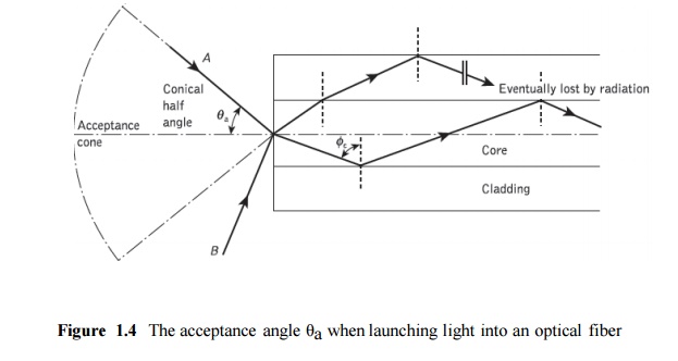
The geometry concerned with launching a light ray into an optical fiber is shown in Figure1.4, which illustrates a meridional ray A at the critical angle φc within the fiber at the core– cladding interface. It may be observed that this ray enters the fiber core at an angle θa to the fiber axis and is refracted at the air–core interface before transmission to the core–cladding interface at the critical angle. Hence, any rays which are incident into the fiber core at an angle greater than θa will be transmitted to the core–cladding interface at an angle less than φc, and will not be totally internally reflected. This situation is also illustrated in Figure 2.4, where the incident ray B at an angle greater than θa is refracted into the cladding and eventually lost by radiation. Thus for rays to be transmitted by total internal reflection within the fiber core they must be incident on the fiber core within an acceptance cone defined by the conical half angle θa.
Hence θa is the maximum angle to the axis at which light may enter the fiber in order to be propagated, and is often referred to as the acceptance angle for the fiber.
If the fiber has a regular cross-section (i.e. the core–cladding interfaces are parallel and there are no discontinuities) an incident meridional ray at greater than the critical angle will continue to be reflected and will be transmitted through the fiber. From symmetry considerations it may be noted that the output angle to the axis will be equal to the input angle for the ray, assuming the ray emerges into a medium of the same refractive index from which it was input.
3. Numerical aperture
The acceptance angle for an optical fiber was defined in the preceding section. However, it is possible to continue the ray theory analysis to obtain a relationship between the acceptance angle and the refractive indices of the three media involved, namely the core, cladding and air. This leads to the definition of a more generally used term, the numerical aperture of the fiber. It must be noted that within this analysis, as with the preceding discussion of acceptance angle, we are concerned with meridional rays within the fiber. Figure 1.5 shows a light ray incident on the fiber core at an angle θ1 to the fiber axis which is less than the acceptance angle for the fiber θa. The ray enters the fiber from a medium (air) of refractive index n0, and the fiber core has a refractive index n1, which is slightly greater than the cladding refractive index n2.
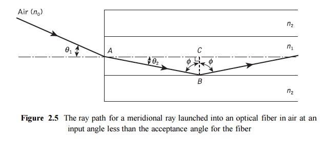
Assuming the entrance face at the fiber core to be normal to the axis, then considering the refraction at the air–core interface and using Snell’s law given by Eq. (1.1):

Considering the right-angled triangle ABC indicated in Figure 2.5, then:

where φ is greater than the critical angle at the core–cladding interface. Hence Eq. (1.3) becomes:

Using the trigonometrical relationship sin2 φ + cos2 φ = 1, Eq. (1.5) may be written in the form:

When the limiting case for total internal reflection is considered, φ becomes equal to the critical angle for the core–cladding interface and is given by Eq. (1.2). Also in this limiting case θ1 becomes the acceptance angle for the fiber θa. Combining these limiting cases into Eq. (1.6) gives:
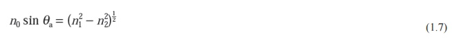
Equation (1.7), apart from relating the acceptance angle to the refractive indices, serves as the basis for the definition of the important optical fiber parameter, the numerical aperture (NA). Hence the NA is defined as:

Since the NA is often used with the fiber in air where n0 is unity, it is simply equal to sin θa. It may also be noted that incident meridional rays over the range 0 ≤ θ1 ≤ θa will be propagated within the fiber. The NA may also be given in terms of the relative refractive index difference between the core and the cladding which is defined as:
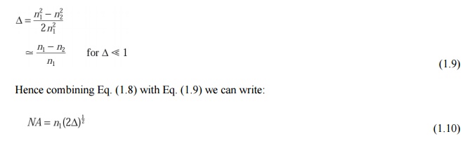
The relationships given in Eqs (1.8) and (1.10) for the numerical aperture are a very useful measure of the light-collecting ability of a fiber. They are independent of the fiber core diameter and will hold for diameters as small as 8 µm. However, for smaller diameters they break down as the geometric optics approach is invalid. This is because the ray theory model is only a partial description of the character of light. It describes the direction a plane wave component takes in the fiber but does not take into account interference between such components. When interference phenomena are considered it is found that only rays with certain discrete characteristics propagate in the fiber core. Thus the fiber will only support a discrete number of guided modes. This becomes critical in small- core-diameter fibers which only support one or a few modes. Hence electromagnetic mode theory must be applied in these cases.
4. Skew rays
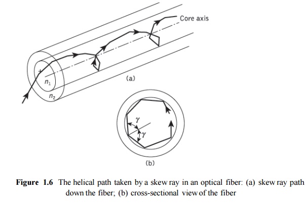
In the preceding sections we have considered the propagation of meridional rays in the optical waveguide. However, another category of ray exists which is transmitted without passing through the fiber axis. These rays, which greatly outnumber the meridional rays, follow a helical path through the fiber, as illustrated in Figure 1.6, and are called skew rays.
It is not easy to visualize the skew ray paths in two dimensions, but it may be observed from Figure 1.6(b) that the helical path traced through the fiber gives a change in direction of 2γ at each reflection, where γ is the angle between the projection of the ray in two dimensions and the radius of the fiber core at the point of reflection. Hence, unlike meridional rays, the point of emergence of skew rays from the fiber in air will depend upon the number of reflections they undergo rather than the input conditions to the fiber. When the light input to the fiber is non uniform, skew rays will therefore tend to have a smoothing effect on the distribution of the light as it is transmitted, giving a more uniform output. The amount of smoothing is dependent on the number of reflections encountered by the skew rays. A further possible advantage of the transmission of skew rays becomes apparent when their acceptance conditions are considered
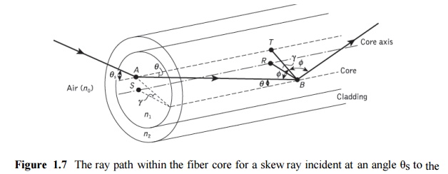
In order to calculate the acceptance angle for a skew ray it is necessary to define the direction of the ray in two perpendicular planes. The geometry of the situation is illustrated in Figure 1.7 where a skew ray is shown incident on the fiber core at the point A, at an angle θs to the normal at the fiber end face. The ray is refracted at the air–core interface before traveling to the point B in the same plane. The angles of incidence and reflection at the pointB are φ, which is greater than the critical angle for the core–cladding interface.
When considering the ray between A and B it is necessary to resolve the direction of the ray path AB to the core radius at the point B. As the incident and reflected rays at the point B are in the same plane, this is simply cos φ. However, if the two perpendicular planes through which the ray path ABtraverses are considered, then γ is the angle between the core radius and the projection of the ray onto a plane BRS normal to the core axis, and θ is the angle between the ray and a line AT drawn parallel to the core axis. Thus to resolve the ray path AB relative to the radius BR in these two perpendicular planes requires multiplication by cos γ and sin θ
Hence, the reflection at point B at an angle φ may be given by:

Using the trigonometrical relationship sin2 φ + cos2 φ = 1, Eq. (2.11) becomes:

If the limiting case for total internal reflection is now considered, then φ becomes equal to the critical angle φc for the core–cladding interface and, following Eq. (2.2), is given by sin φc = n2/n1. Hence, Eq. (2.12) may be written as:
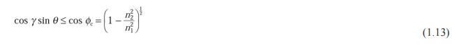
Furthermore, using Snell’s law at the point A, following Eq. (2.1) we can write:

where θa represents the maximum input axial angle for meridional rays, as expressed in Section 1.2.2, and θ is the internal axial angle. Hence substituting for sin θ from Eq.(1.13) into Eq. (1.14) gives:
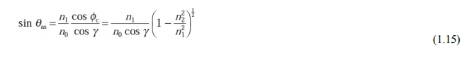
where θas now represents the maximum input angle or acceptance angle for skew rays. It may be noted that the inequality shown in Eq. (1.13) is no longer necessary as all the terms in Eq. (1.15) are specified for the limiting case. Thus the acceptance conditions for skew rays are:
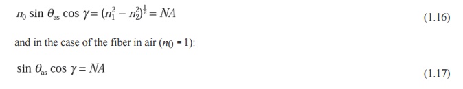
Therefore by comparison with Eq. (1.8) derived for meridional rays, it may be noted that skew rays are accepted at larger axial angles in a given fiber than meridional rays, depending upon the value of cos γ. In fact, for meridional rays cos γ is equal to unity and θas becomes equal to θa. Thus although θa is the maximum conical half angle for the acceptance of meridional rays, it defines the minimum input angle for skew rays. Hence, as may be observed from Figure 1.6, skew rays tend to propagate only in the annular region near the outer surface of the core, and do not fully utilize the core as a transmission medium. However, they are complementary to meridional rays and increase the light-gathering capacity of the fiber. This increased light-gathering ability may be significant for large NA fibers, but for most communication design purposes the expressions given in Eqs (1.8) and (1.10) for meridional rays are considered adequate.
Related Topics