Chapter: Civil : Railway Airport Harbour Engineering : Railway Engineering : Signalling and Interlocking
Railway Interlocking
Interlocking
Interlocking is a device or a
system meant to ensure the safety of trains. With the increase in the number of
points and the signals and introduction of high speeds, it has become necessary
to eliminate human error, which would otherwise lead to massive losses of life
and property. The points and signals are set in such a way that the cabin man
cannot lower the signal for the reception of a train unless the corresponding
points have been set and locked. The signal is thus interlocked with the points
in a way that no conflicting movement is possible and the safety of trains is
ensured.
Interlocking can, therefore, be
defined as an arrangement of signals, points, and other apparatus so
interconnected by means of mechanical or electrical locking that they can be
operated in a predetermined sequence to ensure that there is no conflicting
movement of signals and points and trains run safely.
The signal and interlocking
system is so designed that the failure of any equipment results in the turning
on of the signal, thus ensuring train safety.
1 Essentials
Lever frames and other apparatus
provided for the operation and control of signals, points, etc., must be so
interlocked and arranged as to comply with the following essential regulations.
(a) It should
not be possible to turn a signal off unless all points for the line on which
the train is to be received are correctly set, all the facing points are
locked, and all interlocked level crossings are closed and inaccessible to road
traffic.
(b) The line
should be fully isolated before the signal is turned off, i.e., no loose wagons
should be able to enter this line.
(c) After the
signal has been turned off, it should not be possible to make adjustments in
the points or locks on the route, including those in the isolated line. Also,
no interlocked gates should be released until the signal is replaced in the
'on' position.
(d) It should
not be possible to turn any two signals off at the same time, as this can lead
to conflicting movements of the trains.
(e) Wherever
feasible, the points should be so interlocked as to avoid any conflicting movement.
2 Standards
The speed of a train depends on a
number of factors such as the haulage capacity of the locomotive, the fitness
of the track, the fitness of the rolling stock, the load of the train, etc.,
and the speed for a particular section is determined based on all these
factors. Depending upon the maximum speeds permitted in a section, the stations
are interlocked in keeping with the prevalent standards, and signalling
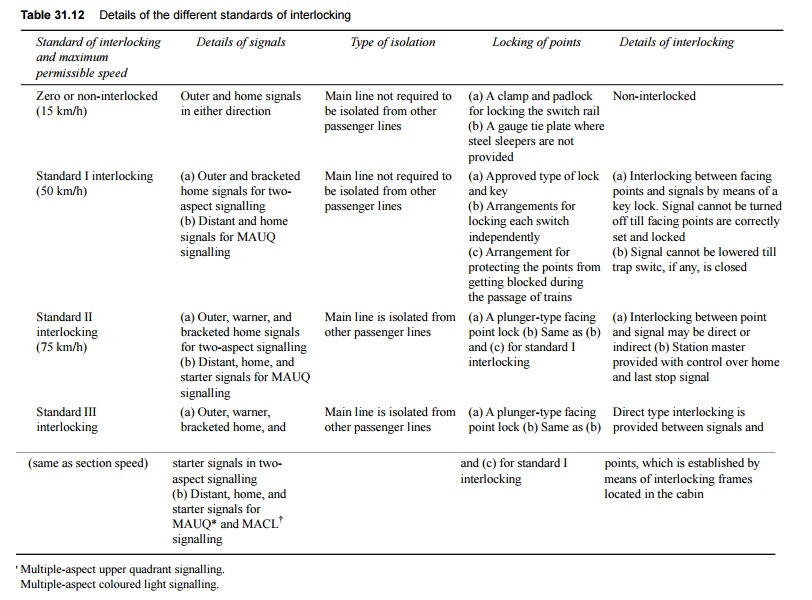
equipment and other facilities are provided accordingly. There are four standards
of interlocking based on the maximum permissible speeds prevailing on Indian
Railways. These refer to the speeds over the main line with respect to the
facing points and the yard.
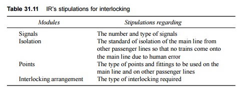
Table 31.11 lists the
stipulations laid down by Indian Railways for signals, isolation, points, and
interlocking arrangements. The details of each of these interlocking standards
are enumerated in Table 31.12.
Table 31.11 IR's stipulations for
interlocking
3 Methods
There are basically two methods of interlocking as explained
below.
Key interlocking
Key interlocking is the simplest
method of interlocking and still exists on branch lines of small stations on
Indian Railways. The method involves the manipulation of keys in one form or
the other. This type of interlocking is normally provided with standard I
interlocking with a speed limit below 50 km/h. The simplest arrangement of key
interlocking is accomplished in the following manner.
(a) Take the
example of a station with a main line and a branch line. The point can be set
either for the main line or branch line.
(b) The point
has two keys. The first is key A, which can be taken out when the point is set
and locked for the main line. Similarly, key B can be taken out when the point
is set and locked for the loop line. At any given time either key A or key B
can be taken out, depending upon whether the route is set for the main line or
the loop line.
(c) The lever
frame operating the signals is provided with two levers. The lever concerning
the main line signal can be operated only by key A and similarly the branch
line signal lever can be operated only by key B.
(d) If the
train is to be received on the main line, the points are set and locked for the
main line and key A is released. This key is used for unlocking the main line
signal lever, thus lowering the signal for the main line. Since key A cannot be
used for interlocking and lowering the branch line signal, only the appropriate
signal can be turned off. This type of interlocking is called
indirect
locking.
In case more than one point is to
be operated, the key released at the first point is used to unlock and operate
the second point and so on. The key released at the last point can then be used
for unlocking the lever operating the appropriate signal. This type of
interlocking is also known as succession locking and is also used for
checking conflicting movements in shunting operations. There are other methods
of interlocking with the help of keys, but all of them involve considerably
lengthy trips from the point to the signal levers and from point to point,
thereby leading to delays. Such arrangements are, therefore, satisfactory only
for stations that handle very light traffic.
Table 31.12 Details of the different
standards of interlocking
Mechanical interlocking
Mechanical interlocking or
interlocking on lever frames is an improved form of interlocking compared to
key locking. It provides greater safety and requires less manpower for its
operation. This method of interlocking is done using plungers and tie bars. The
plungers are generally made of steel sections measuring 30 cm � 1.6 cm and have
notches in them. The tie bars are placed at right angles to the plungers and
are provided with suitably shaped and riveted pieces of cast iron or steel that
fit exactly in the notches of the tappets.
The main components of an
interlocking system are a locking frame, point fittings, signal fittings, and
connecting devices for connecting the locking frame to the point and signal
fittings. The locking frame consists of a number of levers, which work various
points, point locks, signal levers, etc. The levers are arranged together in a
row in a frame. Pulling a point lever operates the point to which it is
connected through a steel rod. Similarly, pulling a signal lever changes the
indication of the signal by pulling the wire connecting the lever and the
signal. To each lever is attached a plunger which has suitably shaped notches
to accommodate the locking tappets. The entire arrangement is provided in a
locking trough where tappets are provided, which move at right angles to the
plungers.
When a lever is pulled, it causes
the plunger to which it is connected to move. Due to wedge action, the
tappet accommodated in the notch of the plunger is pushed out at right angles
to the movement of the plunger. The motion is transmitted to all other tappets
that are connected to this tappet through a tie bar. As a result of this
motion, the other tappets either get pushed into or out of the respective notches
of the other plunger depending upon the type of interlocking provided. In case
the other tappet is free but slips inside the notch of the other plunger, it
locks the lever connected to this plunger. In consequence, the other lever gets
locked in that position and cannot be operated. However, if the tappet was
earlier positioned in the notch of the plunger, thereby locking the lever, and
is now out of the notch, the other lever becomes free to be operated.
4 Different Cases
The following cases of interlocking are encountered in
practical application.
Normal locking In this
case, pulling one lever locks the other lever in its normal position.
Back locking or release locking In this
case, when the lever is in its normal position, it also blocks the other
lever in its normal position, but when this lever is pulled it releases the
other lever, which can then also be pulled. Furthermore, once the second lever
is also pulled, the first lever gets locked in the 'pulled' position and cannot
be returned to its normal position unless the second lever is restored to its
normal position.
Both wall locking In this
case, once a lever is pulled, it locks the other lever in its current
position, i.e., in the normal or pulled position.
Special or conditional locking In this
case, the pulling of one lever locks the other lever only when certain
conditions are fulfilled, say the third lever being in a normal or pulled
position as the case may be.
5 Mechanical Interlocking of Points and
Signals of a Two-line Railway Station
To understand the mechanical
interlocking of the points and signals of a two-line railway station, let us
take the case of a typical railway station that has both a main line and a loop
line. It is provided with a home signal 1 operated by lever 1 for the main line
and a home signal 2 operated by lever 2. Point 3 is set for the main line when
lever 3 is in its normal position and for the loop line when lever 3 is pulled.
In its pulled position lever 4 locks point 3 in either position (normal or reverse)
by pushing the plunger of the facing point into the 'lock in' position. The
essentials of this interlocking system are as follows (Fig. 31.21).
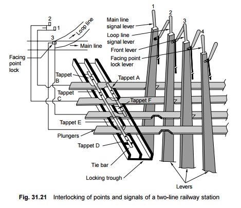
(a) It should
not be possible to turn off both the signals, i.e., 1 and 2 at the same time,
i.e., the train should be received either on the main line or the loop line at
any given time. To achieve this, tappet A is forced out of the plunger of lever
1 when lever 1 is pulled. The tappet enters the notch of the plunger of lever 2
and cannot move out until lever 1 is pulled. This prevents lever 2 from getting
pulled when lever 1 is pulled. The reverse of this situation is also true.
(b) It should
not be possible to turn a signal off until and unless the point is set and
locked. If an effort is made to pull either lever 1 or 2, the same cannot be
pulled. This is because of the following reasons. Tappets B and C are rivetted
with a tie bar that is in turn connected with tappet D. Since tappet D is
butting against the face of the plunger of lever 4, tappet B or C cannot be
moved. This plunger can move only when lever 4 is pulled, thereby bringing the
notch of the plunger opposite tappet D. Once this happens, it is not possible
to restore the position of lever 4 till lever 1 or 2 has been brought back to
its normal position. This is a case of release locking. Levers 1 and 2
are released by pulling lever 4, which in turn locks the point.
(c) Lever 4
is a lock lever and locks point 3 in either position. The same can be
visualized for tappet E.
(d) Similarly,
the main line home signal lever 1 cannot be pulled if point lever 3 is pulled,
i.e., if it is set for the loop line, as the tappet F cannot be pushed, which
allows lever 1 to be pulled when the notch in the plunger of lever 3 that lies
opposite tappet F has been shifted from its position due to the pulling of
lever 3. With lever 3 normal, lever 1 can be pulled conveniently,
simultaneously resulting in the locking of lever 2 in it normal position by
tappet A.
This example indicates that, with
proper planning, it is possible to mechanically interlock the movement of
points and signals and thus ensure complete safety.
6
Electrical Interlocking of Points
and Signals of a Two-line Railway Station
Electrical interlocking is
achieved through electric switches known as relays. The manipulation of relays
achieves interlocking, whereas lever locks that are attached with the levers in
place of plungers or in addition to plungers prevent a lever from getting
pulled, or allow it to get pulled or normalized if the interlocking so permits.
Relays use the simple principle
of electromagnetism, whereby a soft iron core wrapped inside a wire coil turns
into electromagnet when current is passed through the wire. An armature is
attached to this electromagnet, which has a number of finger contacts that come
into contact with each other when the armature is attracted to the magnet and
break the contact when the armature is not attracted to it. The whole system is
housed in a glass or metal box and is known as relay.
Related Topics