Chapter: Civil : Railway Airport Harbour Engineering : Railway Engineering : Curves and Superelevation
Railway Engineering Curves and Super elevation: Circular Curves
Curves and Super elevation - Introduction
Curves are introduced on a
railway track to bypass obstacles, to provide longer and easily traversed
gradients, and to pass a railway line through obligatory or desirable
locations. Horizontal curves are provided when a change in the direction of the
track is required and vertical curves are provided at points where two
gradients meet or where a gradient meets level ground. To provide a comfortable
ride on a horizontal curve, the level of the outer rail is raised above the
level of the inner rail. This is known as superelevation.
Circular Curves
This section describes the
defining parameters, elements, and methods of setting out circular curves.
Radius or degree of a curve
A curve is defined either by its
radius or by its degree. The degree of a curve (D) is the angle
subtended at its centre by a 30.5-m or 100-ft chord.
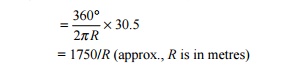
The value of the degree of the curve can be
determined as indicated below. Circumference of a circle = 2p R
Angle
subtended at the centre by a circle with this circumference = 360 o
Angle
subtended at the centre by a 30.5-m chord, or degree of curve
In cases where the radius is very
large, the arc of a circle is almost equal to the chord connecting the two ends
of the arc. The degree of the curve is thus given by the following formulae
D = 1750/R (when R is
in metres) D = 5730/R (when R is in feet)
A 2 o
curve, therefore, has a radius of 1750/2 = 875 m.
Relationship between radius and versine
of a curve
The
versine is the perpendicular distance of the midpoint of a chord from the arc
of a circle. The relationship between the radius and versine of a curve can be
established as shown in Fig. 13.1. Let R be the radius of the curve, C
be the length of the chord, and V be the versine of a chord of length C.
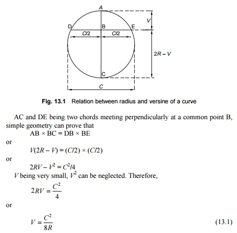
In Eqn (13.1), V, C,
and R are in the same unit, say, metres or centimetres. This general
equation can be used to determined versines if the chord and the radius of a
curve are known.
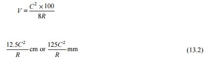
Case I:
Values in metric units Formula (13.1) can also be written as

where R
is the radius of the curve, C is the chord length in metres, and V
is the versine in centimetres, or
Case II:
Values in fps units When R1 is the
radius in feet, C1 is the chord length in
feet, and V1 is the versine in inches, Formula (13.1) can be
written as
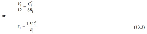
Using formulae (13.2) and (13.3),
the radius of the curve can be calculated once the versine and chord length are
known.
Determination of degree of a curve in
field
For determining the degree of the
curve in the field, a chord length of either 11.8 m or 62 ft is adopted. The
relationship between the degree and versine of a curve is very simple for these
chord lengths as indicated below.
Versine
on a 11.8-m chord
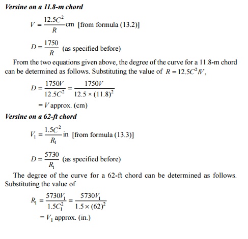
This important relationship is
helpful in determining the degree of the curve at any point by measuring the
versine either in centimetres on a 11.8-m chord or in inches on a 62-ft chord.
The curve can be of as many degrees as there are centimetres or inches of the
versine for the chord lengths given above.
Maximum Degree of a Curve The
maximum permissible degree of a curve on a track depends on various
factors such as gauge, wheel base of the vehicle, maximum permissible
superelevation, and other such allied factors. The maximum degree or the
minimum radius of the curve permitted on Indian Railways for various gauges is
given in Table 13.1.
Table
13.1 Maximum
permissible degree of curves

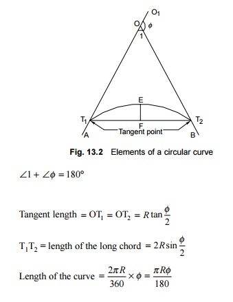
Elements of a circular curve
In Fig.
13.2, AO and BO are two tangents of a circular curve which meet or intersect at
a point O, called the point of intersection or apex. T1 and T2
are the points where the curve touches the tangents, called tangent points
(TP). OT1 and OT2 are the tangent lengths of the curve
and are equal in the case of a simple curve. T1T2 is the
chord and EF is the versine of the same. The angle AOB formed between the
tangents AO and OB is called the angle of intersection ( �1) and the angle BOO1 is the angle of deflection
(�f) . The following are some of the
important relations between these elements:
1.Setting Out a Circular
Curve
A
circular curve is generally set out by any one of the following methods.
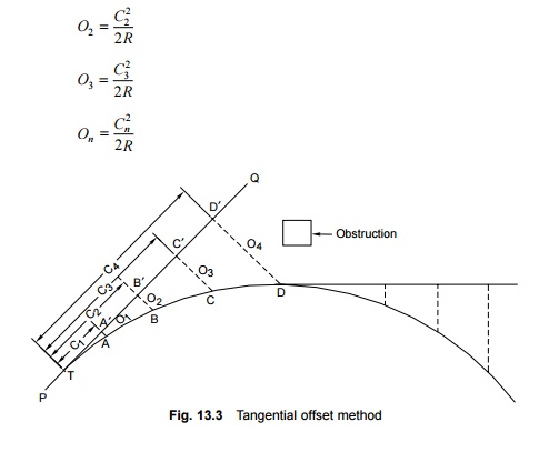
Tangential
offset method
The tangential offset method is employed for setting out a
short curve of a length of about 100 m (300 ft). It is generally used for
laying turnout curves.
In Fig.
13.3, let PQ be the straight alignment and T be the tangent point for a curve
of a known radius. Let AA � , BB� , CC � , etc. be perpendicular
offsets from the tangent. It can be proved that
Value of
offset O1 =
C12= 2R
where C1
is the length of the chord along the tangent. Similarly,
The various steps involved in the
laying out of a curve using this method are as follows.
(a) Extend
the straight alignment PT to TQ with the help of a ranging rod. TQ is now the
tangential direction.
(b) Measure
lengths C1, C2, C3, etc.
along the tangential direction and calculate the offsets O1, O2,
O3, etc. for these lengths as per the formulae given above.
For simplicity, the values of C1, C2, C3,
etc. may be taken in multiples of three or so.
(c) Measure
the perpendicular offsets O1, O2, O3,
etc. from the points A, B, C,
�
, B� , C� , etc. on the curve.
In practice, sometimes it becomes
difficult to extend the tangent length beyond a certain point due to the
presence of some obstruction or because the offsets become too large to measure
accurately as the length of the curve increases. In such cases, the curve is
laid up to any convenient point and another tangent is drawn out at this point.
For laying the curve further, offsets are measured at fixed distances from the
newly drawn tangent.
Long chord offset method
The long chord offset method is
employed for laying curves of short lengths. In such cases, it is necessary
that both tangent points be located in such a way that the distance between
them can be measured, and the offsets taken from the long chord.
In Fig.
13.4, let T1T2 be the long chord of a curve of radius R.
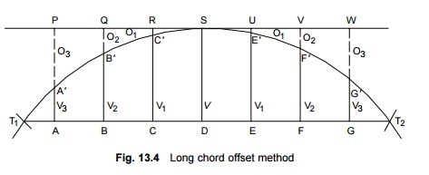
Let the length of the long chord
be C and let it be divided into eight equal parts T1 A, AB,
BC, CD, etc., where each part has a length x = C/8. Let PW be a
line parallel to the long chord and let O1, O2,
and O3 be the offsets taken from points R, Q, and P.
Versine V
from the long chord C is calculated by the formula
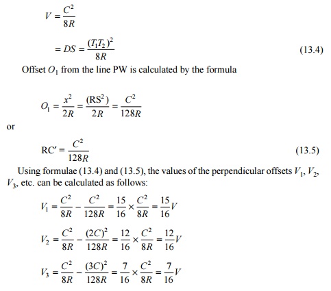
During fieldwork, first the long
chord is marked on the ground and its length measured. Then points A, B, C,
etc. are marked by dividing this long chord into eight equal parts. The values
of the perpendicular offsets V1, V2, V3, etc.
are then calculated and the points A� , B� , C�, etc. identified on the
curve.
Quartering of versine method
The
quartering of versine method (Fig. 13.5) is also used for laying curves of
short lengths, of about 100 m (300 ft). In this method, first the location of
the two tangent points (T1 and T2) is determined and then
the distance between them is measured. The versine (V) is then
calculated using the formula
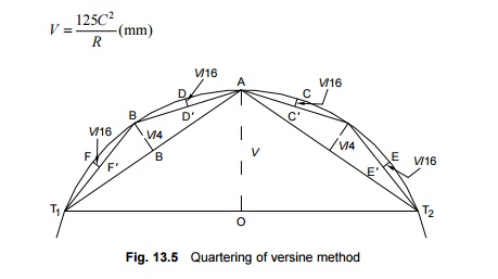
V is
measured in the perpendicular direction at the central point O of the
long chord. The tangent points T1 and T2 are
joined and the distance AT1 measured. As AT1 is almost
half the length of chord T1T2 and as versines are
proportional to the square of the chord, the versine of chord AT1 is
V/4.
For laying the curve in the
field, the versine V/4 is measured at the central point B on chord AT1
and the position of point B is thus fixed. Similarly, a point is also fixed on
the second half of the curve. AB is further taken as a sub-chord and the
versine on this sub-chord is measured as V/16. In this way the points D
and F are also fixed. The curve can thus be laid by marking half-chords and
quartering the versines on these half-chords.
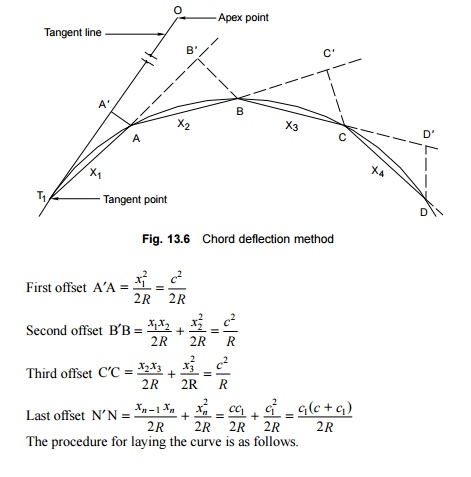
Chord deflection method
The chord
deflection method of laying curves is one of the most popular methods with
Indian Railways. The method is particularly suited to confined locations, as
most of the work is done in the immediate proximity of the curves. In Fig.
13.6, let T1 be the tangent point and A, B, C, D, etc. be successive
points on the curve. Let X1, X2, X3 and X4
be the length of chords T1A, AB, BC, and CD. In practice, all the
chords are of equal length. Let the value of these chords be c. The last
chord may be of a different length. Let its value be c1. It
can be proved that
1. The
position of the tangent point T1 is located by measuring a distance
equal to the tangent length R tan f/2 from
the apex point O. In this case, f is the
deflection angle.
2. A length
equal to the first chord (c) is measured along the tangent line T1O
and point A� is marked.
3. The zero
end of the tape is placed at the tangent point T1. It is then swung
and the arc A1A marked. Then the first offset on the arc is
measured. The value of the offset is c2/2R. The
position of point A is thus fixed.
4. The chord
T1A is extended to point B and AB� is marked
as the second chord length equal to c.
5. The
position of point B is then fixed on the curve since the value of the second
offset is known and is equal to c2/R.
6. Similarly,
the positions of other points C, D, etc. are also located.
7. The last
point on the curve is located by taking the value of the offset as
c1 (c + c1 )/R ,
where c1 is the length of the last chord.
The various points on the curve
should be set with great precision because if any point is fixed inaccurately,
its error is carried forward to all subsequent points.
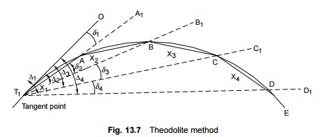
Theodolite method
The theodolite method for setting
out curves is also a very popular method with Indian Railways, particularly
when accuracy is required. This method is also known as Rankine's method of
tangential angles. In this method, the curve is set out using tangential angles
with the help of a theodolite and a chain or a tape.
In Fig.
13.7, let A, B, C, D, etc. be successive points on the curve with lengths
T1A = x1,
AB = x2, BC = x3, CD = x4,
etc. Let d1 , d 2 , d 3
, d4 be the
tangential angles OT1A, AT1B, BT1C, and CT1D
made by the successive chords amongst themselves.
Let D1 , D 2
, D 3 , and D4 be the deflection angles of the chord from the
deflection line.
Angle subtended at centre by a 100-ft chord = D o
Tangential angle for a 100-ft chord = D/2
Tangential
angle for an x-ft chord, d = (D/2)
� (1/100) x degree
= (5730/2R)
� (1/100) � 60 x minutes
= 1719(x/R)
where d is the
deflection angle in minutes, x is the chord length in feet, and R
is
the radius in feet. It is seen that
D1 = d1
D
2 = d 1 + d 2 = D1
+ d2
D
3 = d 1 + d 2 + d 3 = D 2 + d3
The
procedure followed for setting the curve is as follows.
(a) The
theodolite is set on the tangent point T1 in the direction of T2O.
(b) The
theodolite is rotated by an angle d1 , which
is already calculated, and the line T1A1 is set.
(c) The
distance x1 is measured on the line T1A1
in order to locate the point A.
(d) Now the
theodolite is rotated by a deflection angle d2 to set
it in the direction of T1B1 and point B is located by
measuring AB as the chord length x2.
(e) Similarly,
the other points C, D, E, etc. are located on the curve by rotating the
theodolite to the required deflection angles till the last point on the curve
is reached.
(f) If higher precision is required, the curve can also be set by using two theodolites.
Related Topics