Chapter: Civil : Railway Airport Harbour Engineering : Railway Engineering : Points and Crossings
Railway Engineering: Turnouts
Turnouts
The simplest arrangement of
points and crossing can be found on a turnout taking off from a straight track.
There are two standard methods prevalent for designing a turnout. These
are the (a) Coles method and the (b) IRS method.
These
methods are described in detail in the following sections.
The important terms used in
describing the design of turnouts are defined as follows.
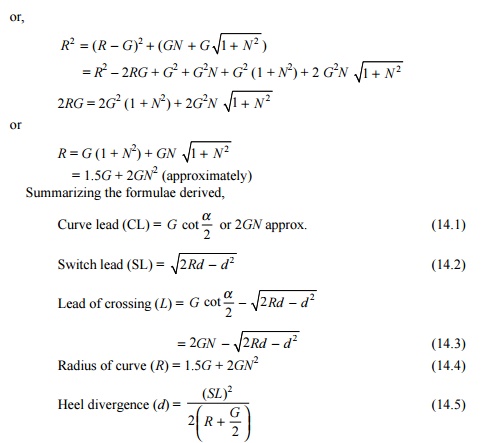
Curve lead (CL) This is
the distance from the tangent point (T) to the theoretical nose of
crossing (TNC) measured along the length of the main track.
Switch lead (SL) This is
the distance from the tangent point (T) to the heel of the switch (TL)
measured along the length of the main track.
Lead of crossing (L) This is
the distance measured along the length of the main track as follows:
Lead of
crossing (L) = curve lead (CL) - switch lead (SL)
Gauge (G) This is the gauge of the track.
Heel divergence (D) This is
the distance between the main line and the turnout side at the heel.
Angle of crossing ( a ) This is
the angle between the main line and the tangent of
the turnout line.
Radius of turnout (R) This is
the radius of the turnout. It may be clarified that the radius of the
turnout is equal to the radius of the centre line of the turnout (R1)
plus half the gauge width.
R = R1
+ 0.5G
As the radius of a curve is quite
large, for practical purposes, R may be taken to be equal to R1.
Special fittings with turnouts
Some of the special fittings required for use with turnouts
are enumerated below.
Distance blocks Special
types of distance blocks with fishing fit surfaces are provided at the
nose of the crossing to prevent any vertical movement between the wing rail and
the nose of the crossing.
Flat bearing plates As
turnouts do not have any cant, flat bearing plates are provided under
the sleepers.
Spherical
washers These are special types of washers and consist of two pieces
with a spherical point of contact between them. This permits the two
surfaces to lie at any angle to each other. These washers are used for
connecting two surfaces that are not parallel to one another. Normally, tapered
washers are necessary for connecting such surfaces. Spherical washers can
adjust to the uneven bearings of the head or nut of a bolt and so are used on
all bolts in the heel and the distance blocks behind the heel on the left-hand
side of the track.
Slide chairs These are
provided under tongue rails to allow them to move laterally. These are
different for ordinary switches and overriding switches.
Grade off chairs These are
special chairs provided behind the heel of the switches to give a
suitable ramp to the tongue rail, which is raised by 6 mm at the heel.
Gauge tie plates These are
provided over the sleepers directly under the toe of the switches, and
under the nose of the crossing to ensure proper gauge at these locations.
Stretcher bars These are provided to
maintain the two tongue rails at an exact distance.
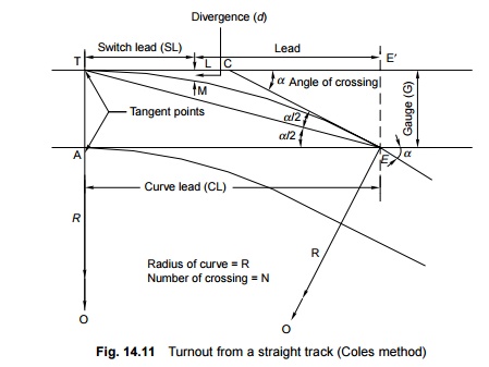
Coles method
This is a
method used for designing a turnout taking off from a straight track (Fig. 14.11).
The curvature begins from a point on the straight main track ahead of the toe
of the switch at the theoretical toe of switch (TTS) and ends at the
theoretical nose of crossing (TNC). The heel of the switch is located at the
point where the offset of the curve is equal to the heel divergence.
Theoretically, there would be no kinks in this layout, had the tongue rail been
curved as also the wing rail up to the TNC. Since tongue rails and wing rails
are not curved generally, there are the following three kinks in this layout.
(a) The first
kink is formed at the actual toe of the switch.
(b) The
second kink is formed at the heel of the switch.
(c) The third
kink is formed at the first distance block of the crossing. The notations used
in Fig. 14.11 are the following.
Curve
lead (CL) = AE = TE'
Switch
lead (SL) = TL
Lead of
crossing (L) = LE'
Gauge of
track (G) = AT = EE'
Angle of
the crossing (a ) = �CEA = �ECE�
Heel of
divergence (d) = LM
Number of
the crossing (N) = cota
Radius of outer rail of turnout curve (R) = OE = OT (O
is the centre of the turnout curve)
Calculations
Curve lead (CL) In DATE ,
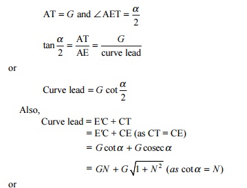
= 2GN
(approximately)
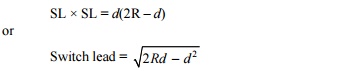
Switch lead (SL) TL is the
length of the tangent with an offset LM = D = heel divergence.
From the properties of triangles, SL � SL = d
(2R - d)
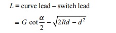
Lead of crossing (L)
L = curve
lead - switch lead
Radius of curve (R) In DAOE ,
OE = OT =
R, OA = R - G
OE2
= OA2 + AE2
OE2
= (R - G) 2 + (curve lead)2
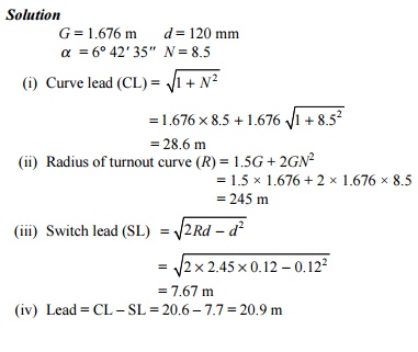
Example
14.1 Calculate the lead and radius of a 1 in 8.5 BG turnout for 90
R rails using Coles method.
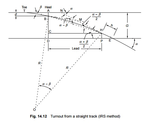
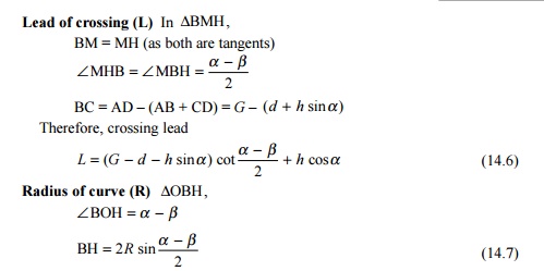
IRS method
In this
layout (Fig. 14.12), the curve begins from the heel of the switch and ends at
the toe of the crossing, which is at the centre of the first distance block.
The crossing is straight and no kink is experienced at this point. The only
kink occurs at the toe of the switch. This is the standard layout used on
Indian Railways. The calculations involved in this method are somewhat
complicated and hence this method is used only when precision is required.
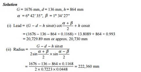
Example
14.2 Calculate the lead and radius of a 1 in 8.5 BG turnout with
straight switches. Use the IRS method.
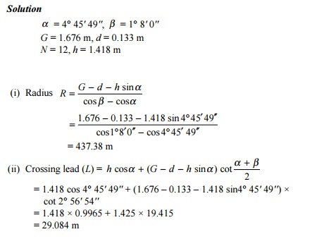
Example
14.3 A turnout is to be laid off a straight BG track with a 1 in 12
crossing. Determine the lead and radius of the turnout with the help of the
following data: heel divergence (d) = 133 mm, crossing angle (a ) = 4 o 45 ' 49'', switch angle ( b ) = 1 o 8 ' 00'', straight length between the
theoretical nose of crossing and the tangent point of crossing (h) =
1.418 m.
Standard turnouts and permissible speeds
On Indian Railways, normally 1 in
8.5 turnouts are used for goods trains while 1 in 12 and 1 in 16 turnouts are
used for passenger trains. Recently 1 in 20 and 1 in 24 turnouts have also been
designed by the RDSO, to be used to permit higher speeds for fast trains on the
turnout side. The maximum speeds permitted on these turnouts are given in Table
14.5.
Table
14.5 Permissible
speeds on turnouts
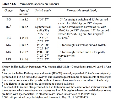
Source: Indian Railway Permanent Way
Manual (IRPWM)-Correction slip no. 94 dated 1 June 2004.
* As per the Indian Railway way
and works (IRWW) manual, a speed of 15 km/h was originally permitted on 1 in
8.5 turnouts. However, due to a subsequent number of derailments of passenger
trains on turn-in curves, the speeds on these turnouts have row been reduced to
10 km/h only.
�
The figures in the second row correspond to curved switches.
� A speed
of 30 km/h is also permitted on 1 in 12 turnouts on those interlocked sections
where all turnouts over which a running train may pass are 1 in 12 throughout
the section and the locomotives are fitted with speedometers. In all other
cases, speed is restricted to 15 km/h only.
� 60 km/h permitted only for high-speed
turnouts to Drg. No. RDST/T-403.
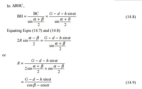
Turnout with Curved Switches
The
following formulae are used for the calculation of turnouts with curved
switches
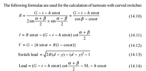
where R is the radius of
the outer lead rail, G is the gauge, h is the lead of the
straight leg of the crossing ahead of TNC up to the TP of the lead curve, t
is the thickness of the switch at the toe, I is the distance from the
toe of the switch to the point where the tangent drawn to the extended lead
curve is parallel to the main line gauge face, V is the distance between
the main line gauge face and the tangent drawn to the lead curve from a
distance l from the toe, y is the vertical ordinate along the Y-axis,
a is the crossing angle, and b is the switch angle.
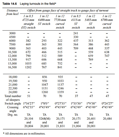
Layout of Turnout
To lay out a turnout in the
field, the values of offsets from the gauge face of the straight track to the
gauge face of the turnout may be adopted from Table 14.6.
Table
14.6 Laying turnouts
in the field*
Related Topics