Chapter: Civil : Railway Airport Harbour Engineering : Railway Engineering : Curves and Superelevation
Railway Engineering: Realignment of Curves
Realignment of Curves
A rail curve is likely to get
distorted from its original alignment with the passage of time due to the
following reasons.
(a) Unbalanced
loading on both the inner and outer rails due to cant excess at slower speeds
or cant deficiency at higher speeds instead of the equilibrium speed for which
the cant has been provided.
(b) Effect of
large horizontal forces exerted on the rails by passing trains. These forces
tend to make a curve flatter at certain locations and sharper at others and the
radius of the curve thus varies from place to place. These result in a rough
ride on the curve due to the change in the radial acceleration from place to
place. Realignment of the curve, therefore, becomes necessary to restore the
smooth running of vehicles on these curves.
1 Criteria for Realignment of Curves
The
Indian Railway Way Manual and the Indian Railway Works Manual had earlier
prescribed that a curve should be realigned when, during an inspection, the
running on a curve is found to be unsatisfactory. No hard and fast rule was
laid as to when a curve should be realigned. Subsequently, the Railway Board
prescribed the following criteria for the realignment of a curve.
Cumulative frequency diagram
For group A and B routes, the
need for curve realignment should be determined by drawing a cumulative
frequency diagram showing the variation of the field versine over the
theoretical versine. The versine variations measured on a 20-m chord should be
limited to 4 mm and 5 mm for group A and B lines, respectively. Realignment
should be taken up when the cumulative percentage of the versines lying within
these limits is less than 80.
Station-to-station versine difference
The type of ride over a curve
depends not only on the difference between the actual and the proposed versine
but also on the station-to-station variation of the actual versine values. The
station-to-station variation of versine determines the rate of change of radial
acceleration, on which the comfort of the ride would depends. The following
stipulations have been made regarding the different gauges adopted on the
Indian Railways.
Broad gauge On curves
where speeds in excess of 100 km/h are permitted, the station-to-station
variation of versines at stations 10 m apart should not exceed 15 mm, and for
speeds of 100 km/h and less, these variations should not exceed 20 mm or 20% of
the average versine of the circular portion, whichever is more.
Metre gauge On curves
which permit speeds in excess of 75 km/h, the station-to-station variation the
versine at stations 10 m apart should not exceed l5 mm. For speeds of 75 km/h
and less, such variations should not exceed 20 mm or 20% of the average versine
of the circular portion, whichever is more.
The decision to completely
realign a curve should be taken after ascertaining the type of ride the curve
provides, on the basis of the cumulative frequency diagram or the distribution
of the variation of versines between stations as described here.
Curve realignment can also be taken up under the following
circumstances.
Unsatisfactory running of track
For other routes, curve
realignment should be taken up when a curve is found to be unsatisfactory as a
result of inspection done by trolley, from the footplate of the locomotive, by
rear carriage, or as a result of various track tests that may have been carried
out.
Local adjustment
When there is an abrupt variation
of versines between adjacent stations, local adjustments should be done to
achieve a versine variation which is within reasonable limits. Such corrections
should be carried out before complete curve realignment is taken up.
2
String Lining Method of Realignment of Curves
The realignment of existing
curves using a theodolite is difficult and laborious work. Therefore, curves
are realigned by measuring the versines with the help of a string and then
correcting these versines. This method is known as the string lining method on
Indian Railways. It is based on the following basic principles.
(a) The sum
of all versines taken on equal chords of any two curves between the same
tangents are equal. It follows that the final value of the sum of the
differences between the existing and proposed versine must be zero.
(b) The throw
at any station is equal to twice the second summation of the differences of the
proposed and existing versine up to the previous station.
Procedure
Realigning a curve using the
string lining method consists of the following three operations.
1. Survey of
the existing curve for measurement of versines.
2. Computation
of slews, including provision of proper transition and superelevation for the
revised alignment.
3. Slewing
of the curve to the revised alignment.
Survey of existing curves
Existing curves are surveyed as follows.
(a) Versine
readings are taken on the gauge face of the outer rail of the curve at 10-m
intervals, using 20-m chords.
(b) Versine
readings are taken with the help of a nylon fishing cord. The cord is kept
tight and at a preferred distance of 20 mm away from the gauge face side of the
outer rail, with the help of a special gadget.
(c) Versine
readings should be taken for at least six stations beyond the apparent tangent
point.
Computation of slews
Slews are computed as follows.
1. The length
of the transition curve is determined based on the permissible speed and degree
of curvature as per standard practice. The versine gradient, i.e., the rate of
change of versine per unit length, is then calculated once the length of the
transition curve and the theoretical versine proposed to be adopted are known.
After calculating the versine gradient, the versines proposed to be adopted for
the transition length can be easily computed.
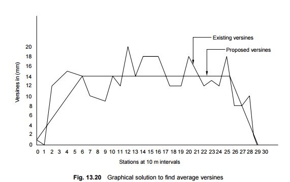
2. The
theoretical ideal versine proposed to be adopted for the transition length is
calculated either exactly by detailed mathematical calculations or
approximately by geometrical methods. In the geometrical method, the versines
are plotted on a graph with respect to the number of stations and an average
figure of versines is estimated by drawing a mean line in between the peaks and
depressions of the graph as shown in Fig. 13.20.
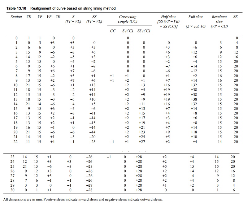
3. A tabular
statement is then prepared as shown in Table 13.10. In this table, the station
numbers and existing versines (VE) are given in columns 1 and 2. The versines
proposed to be adopted (VP) for the circular curve as well as for the
transition length, as calculated before, are given in column three. It should
be ensured that the sums of the proposed and existing versines are equal.
4. Versine
differences between the existing and proposed versines (VP - VE) are then
calculated for each station and given in column 6, shifting it by half the
station.

5. The first
summation of the versine difference is S(VP - VE) written in column 5 and in
between, shifting is done by half the station, i.e., nth row of column 5
+ (n + 1)th row of column 4 = (n + 1)th row of column 5-this must
be zero in the end.
6. The
second summation of versines SS(VP - VE) is calculated by adding to it the first
summation of versine difference. This is written in column 6, shifting it by
half the station again. It should be ensured that the second summation of the
difference of versines, which is also equal to half the slew, is zero at the
first and last stations and at obligatory points, if any. If this condition is
not satisfied, correcting couples are applied as described next.
7. The
correcting couples (CC) are applied (column 7) by changing the proposed
versines in such a way that this brings down the second summation of the
difference of versines at one place and makes the second summation negative at
another place, keeping a proper distance, i.e., the correct number of stations,
in between.
The first and second summations of the correcting
couples, S(CC) and SS(CC), are given is done in columns 8 and 9, respectively.
The correcting couple is applied depending upon the value of the second
summation of versine difference derived against the last station, so that the
final value, after adding the effect of the couple, becomes zero. Similarly,
correcting couples are applied to control the slews at obligatory points.
Otherwise too, slews must be limited to the minimum possible values in the
entire curve.
8. The
resultant half slews (column 6 + column 9) and full slews (2 � columns 10) are
shown in columns 10 and 11. The final versines (column 3 + column 7) to be
adopted are written in column 12.
9. The value
of cant to be provided, rate of introduction of cant, and points of zero and
maximum cant are also calculated. These are shown in column 13.
Slewing curve to the new alignment
The following points should be
kept in mind when a curve is slewed to the new alignment.
(a) A
positive slew indicates an inward slew and a negative slew indicates an outward
slew.
(b) The curve
should be slewed to an accuracy of �2 mm. After the realignment, the versine of
the new curve should be measured for uniformity.
(c) The
necessary superelevation, which is already determined, should be given to the
curve. The superelevation is zero at the tangent point.
(d) Curve
indication posts should be fixed at important locations for checks to be
carried out during maintenance, if required.
Use of computers for calculation of slew
As the
normal method for calculating slew is slow and tedious, computerizing the same
would be well appreciated. Eastern Railways has already developed two
programs on the IBM 1401 computer, one for calculating slews
for simple curves and the other for calculating the same for compound curves
with obligatory points so as to obtain solutions for curve realignment. The
time taken is computing a realignment solutions for a curve with 150 stations
is about 1.5 minutes. Besides saving time, computerized calculations provide
much better precision.
3 Curve Correctors Cum Recorders
Indian Railways has procured
about 50 curve correctors which continuously record the versines of curves and
help in improving their alignments. The utility of this equipment increases if
it can also be used for measuring gauge variations and unevenness, and this can
be done easily by making suitable modifications to it. Accordingly, the RDSO
has developed special attachments to be used with existing curve correctors for
recording the unevenness and gauge parameters, thus converting the existing
curve correctors into track recorder cum curve correctors. This new equipment
measures the following:
(a) Alignment
over a 10-m chord
(b) Unevenness
over a 10-m chord
(c) Sleeper-to-sleeper
gauge variation
4 Realignment of Curves on Double or
Multiple Lines
On double or multiple tracks, each curve should be string
lined independently. No attempt should be made to realign a curve by slewing it
to a uniform centre-to-centre distance from another realigned curve due to the
following reasons:
(a) The
existing track centres may not be uniform, and a relatively small throw on one
track may entail a much larger (even prohibitively larger) throw on the
adjacent track.
(b) It is
nearly impossible to measure the centre-to-centre distance of curved tracks
along the true radial line, and a small error in the angular direction of
measurement would mean an appreciable error in the true radial distance.
(c) The transition lengths at the entry and exit may measure differently, which make it impracticable to maintain uniform centres on them, even though the degree of the circular curves is nearly the same.
Related Topics