Chapter: Civil : Railway Airport Harbour Engineering : Railway Engineering : Points and Crossings
Railway Engineering: Crossing
Crossing
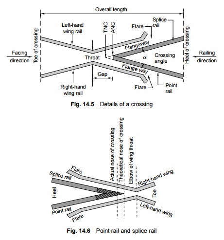
A crossing or frog is a
device introduced at the point where two gauge faces cross each other to permit
the flanges of a railway vehicle to pass from one track to another (Fig. 14.5).
To achieve this objective, a gap is provided from the throw to the nose of the
crossing, over which the flanged wheel glides or jumps. In order to ensure that
this flanged wheel negotiates the gap properly and does not strike the nose,
the other wheel is guided with the help of check rails. A crossing consists of
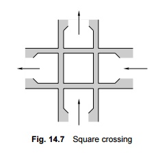
the following components, shown in Fig. 14.6.
(a) Two
rails, the point rail and splice rail, which are machined to form
a nose. The point rail ends at the nose, whereas the splice rail joins it a
little behind the nose. Theoretically, the points rail should end in a point
and be made as thin as possible, but such a knife edge of the point rail would
break off under the movement of traffic. The point rail, therefore, has its
fine end slightly cut off to form a blunt nose, with a thickness of 6 mm
(1/4"). The toe of the blunt nose is called the actual nose of crossing
(ANC) and the theoretical point where gauge faces from both sides intersect is
called the theoretical nose of crossing (TNC). The 'V' rail is planed to
a depth of 6 mm (1/4") at the nose and runs out in 89 mm to stop a
wheel running in the facing direction from hitting the nose.

(b) Two wing
rails consisting of a right-hand and a left-hand wing rail that converge to
form a throat and diverge again on either side of the nose. Wing rails are
flared at the ends to facilitate the entry and exit of the flanged wheel in the
gap.
(c) A pair of
check rails to guide the wheel flanges and provide a path for them, thereby
preventing them from moving sideways, which would otherwise may result in the
wheel hitting the nose of the crossing as it moves in the facing direction.
1 Types of Crossings
A crossing may be of the following types.
(a) An acute
angle crossing or 'V' crossing in which the intersection of the two gauge
faces forms an acute angle. For example, when a right rail crosses a left rail,
it makes an acute crossing. Thus, unlike rail crossings form an acute crossing
(A and C of Fig. 15.9).
(b) An obtuse
or diamond crossing in which the two gauge faces meet at an obtuse
angle. When a right or left rail crosses a similar rail, it makes an obtuse
crossing (B and D of Fig. 15.9).
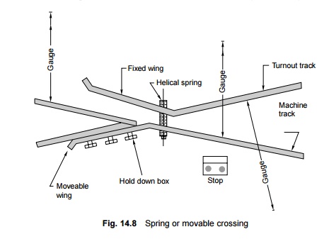
A square
crossing in which two tracks cross at right angles. Such crossings are
rarely used in actual practice (Fig. 14.7).
For
manufacturing purposes, crossings can also be classified as follows.
Built up crossing In a
built-up crossing, two wing rails and a V section consisting of splice
and point rails are assembled together by means of bolts and distance blocks to
form a crossing. This type of crossing is commonly used on Indian Railways.
Such crossings have the advantage that their initial cost is low and that
repairs can be carried out simply by welding or replacing each constituent
separately. A crossing becomes unserviceable when wear is more than 10 mm
(3/8"). A built-up crossing, however, lacks rigidity. The bolts require
frequent checking and sometimes break under fast and heavy traffic.
Cast steel crossing This is a
one-piece crossing with no bolts and, therefore, requiring very little
maintenance. Comparatively, it is a more rigid crossing since it consists of
one complete mass. The initial cost of such a crossing is, however, quite high
and its repair and maintenance pose a number of problems. Recently cast
manganese steel (CMS) crossings, which have longer life, have also been
adopted.
Combined
rail and cast crossing This is a combination of a built-up and cast
steel crossing and consists of a cast steel nose finished to ordinary rail
faces to form the two legs of the crossing. Though it allows the welding of
worn out wing rails, the nose is still liable to fracture suddenly.
2 CMS Crossing
Due to increase in traffic and
the use of heavier axle loads, the ordinary built-up crossings manufactured
from medium-manganese rails are subjected to very heavy wear and tear,
specially in fast lines and suburban sections with electric traction. Past
experience has shown that the life of such crossings varies from 6 months to 2
years, depending on their location and the service conditions. CMS crossings
possess higher strength, offer more resistance to wear, and consequently have a
longer life. The following are the main advantages of CMS crossings.
(a) Less wear
and tear.
(b) Longer
life: The average life of a CMS crossing is about four times more than that of
an ordinary built-up crossing.
(c) CMS
crossings are free from bolts as well as other components that normally tend to
get loose as a result of the movement of traffic.
These days CMS crossings are
preferred on Indian Railways. Though their initial cost is high, their
maintenance cost is relatively less and they last longer. However, special care
must be taken in their laying and maintenance. Keeping this in view, CMS crossings
have been standardized on Indian Railways. On account of the limited
availability of CMS crossings in the country, their use has, however, been
restricted for the time being to group A routes and those lines of other routes
on which traffic density is over 20 GMT. These should also be reserved for use
on heavily worked lines of all the groups in busy yards.
3 Spring or Movable Crossing
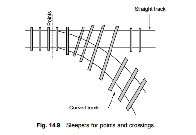
In a
spring crossing, one wing rail is movable and is held against the V of the
crossing with a strong helical spring while the other wing rail is fixed (Fig.
14.8). When a vehicle passes on the main track, the movable wing rail is snug
with the
crossing and the vehicle does not
need to negotiate any gap at the crossing. In case the vehicle has to pass over
a turnout track, the movable wing is forced out by the wheel flanges and the
vehicle has to negotiate a gap as in a normal turnout.
This type of crossing is useful
when there is high-speed traffic on the main track and slow-speed traffic on
the turnout track.
4 Raised Check Rails for Obtuse Crossings
In order to provide a guided
pathway in the throat portion of a 1 in 8.5 BG obtuse diamond crossing, the
check rails are raised by welding a 25-mm-thick MS plate. This arrangement is
considered satisfactory for BG as well as MG routes.
5 Position of Sleepers at Points and
Crossings
Sleepers
are normally perpendicular to the track. At points and crossings, a situation
arises where the sleepers have to cater to the main line as well as to the
turnout portion of the track. For this purpose, longer sleepers are used for
some length of the track as shown in Fig. 14.9.
Related Topics