Chapter: Civil : Railway Airport Harbour Engineering : Railway Engineering : Rails
Rail Flaw Detection
Rail Flaw
Detection
A defect in a rail which will ultimately lead to the fracture
or breakage of the rail is called a flaw. From the point of view of the
ultimate consequence of the flaw resulting in a fracture, it is necessary to
detect these flaws and take timely action to remove them. Rail flaws can be
detected either by visual examination of the rail ends or by rail flaw
detection equipment.
Visual examination of rail ends In this
method, the joint is first opened after removing the fish plates. The
rail ends are then cleaned using kerosene oil and visually examined in detail
with the help of a magnifying glass for any hair crack, etc. White chalk is
sometimes rubbed on the rail ends so as to identify the flaw clearly. A mirror
is used to reflect light on the joint in case sufficient light is not
available.
Ultrasonic rail flaw detectors Ultrasonic
rail flaw detectors (USFDs) have been progressively used in recent years
on Indian Railways for the detection of flaws. This method is also known as the
non-destructive method of testing rails.
1
Theory of Ultrasonic Rail Flaw Detectors
Vibration waves of a frequency of more than 20,000 cycles per
second are termed as ultrasonic waves. These waves have the property of being
able to pass through materials and following the normal principles of light
waves of refraction, reflection, and transmission. Whenever there is a change
of medium, some of the ultrasonic energy gets reflected and the rest gets
transmitted. The amount of energy reflected depends upon the physical
properties of the two media. When travelling through steel, if these waves come
across air either from the bottom of the steel or from any flaw inside the
steel, the reflection is almost 100%. This property has been found most useful
for detecting flaws in rails. Thus, when ultrasonic waves are fed from a
location on a rail, they pass through the rail metal and are normally reflected
only from the foot. However, if a discontinuity exists in the rail metal due to
some flaw, the ultrasonic waves get reflected back from the location of the
flaw, which can be picked up and the defect located.
Production
of ultrasonic waves
There are several methods of
producing ultrasonic energy. The most common and simple method of producing
ultrasonic frequency is by using ' crystal transducers', which normally
produce ultrasonic waves of a frequency of up to 15 MHz. The crystals generally
used for this purpose are made either of quartz or of barium titanate, cut to
special size, shape, and dimensions. These crystals have the peculiar property
of changing dimensions and generating vibrations in a particular direction when
an oscillating electric charge is applied to the crystal faces. Also, when
these crystals are made to vibrate, they produce an oscillating electric
current. The crystals, as such, have the potential of generating ultrasonic
vibrations, as also of converting the waves received after reflection into
electric current. They also possess reversible properties.
These crystals are housed in
metal holders protected by superior quality Perspex and then termed probes.
There are two types of probes used for ultrasonic testing.
Normal probe This
probe consists of two semi-cylindrical thin crystals with a vertical
separating layer through the crystals and Perspex. These probes transmit
ultrasonic waves vertically downwards when put on the rail and are suitable for
detecting horizontal or inclined flaws, including bolt hole cracks.
Angle probe In this
probe, crystals are mounted on an angular surface capable of transmitting
pulses at an outward angle, which may be forward or backward or both, with
separate transmitting and receiving crystals. The waves emitted by these probes
follow an inclined path and are suited to detect inclined and vertical defects.
Techniques of ultrasonic testing
A number of techniques have been
used in ultrasonic testing to suit the design of different equipment. Some of
these techniques are the following.
(a) Frequency
modulation
(b) Pulse
echo
(c) Transmission
(d) Resonance
(e) Acoustic
range
Indian Railways uses the frequency
modulation and pulse echo techniques and only these are discussed in detail
here.
Frequency modulation technique In
instruments utilizing frequency modulation ultrasonic waves are created
with the help of a probe crystal and transmitted continuously into the rail at
rapidly changing frequencies. It is necessary for the rail head to be wet to
enable the ultrasonic waves to pass efficiently from the crystal to the rail.
The waves that get reflected from the opposite face are received continuously
by the crystal. There is interference between the transmitted waves and the
reflected waves, which causes resonance. As the frequencies of the transmitted
waves are changing constantly, such resonance takes place at regular intervals.
When the position of reflection is changed due to a flaw in the metal, the
resonance gets affected, which can be easily detected by the operator.
Instruments manufactured on this principle such as the Audi-gauge are light,
portable, and simple in mechanism. However, these instruments have certain
limitations.
Fine vertical cracks are not readily detected because the
single vertical probe does not find any surface defect from which it can be
reflected.
(b) Cracks
wholly below bolt holes are also not detected, as the vibrations are
interrupted by the hole.
Pulse echo system In the
pulse echo technique, a pulsed ultrasonic beam of very high frequency is
produced by a pulse generator and sent in to the rail. At the opposite face,
the ultrasonic waves are reflected and the echo is picked up by the crystal
transducers. A discontinuity or defect in the rail will also produce the echo.
The time interval between the initial pulse and the arrival of the echoes is measured
with the help of a cathode ray tube. There may be multiple reflections of the
echo but the one arising due to a fault can easily be determined by its
relative position and amplitude.
The more sophisticated types of
instruments that are based on the pulse echo system are being manufactured by
the firm Kraut Kramer at present.
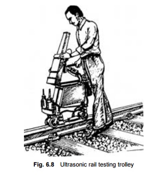
2 Kraut Kramer Multi Probe Rail Testing
Trolley
This is the most common type of
equipment used on Indian Railways for detecting flaws in the rail Fig. 6.8. The
equipment is fitted on a hand trolley that is carried on the rails. There are
two probes: a normal probe and an angle probe, both act independently. The
probe material used for the production of ultrasonic waves is barium titanate,
which produces and transmits vertical ultrasonic waves of four megacycles
frequency through the vertical probe and 2 mega cycles frequency through the
angle probe. The cylindrical probe is mounted on a knuckle jointed holder frame
and has a renewable bakelite wear plate at the base. As the probe is worked
over the rail, the bakelite piece takes the wear completely. The height of the
probe above the rail surface can be adjusted in the holder assembly. The normal
probe is powerful enough to scan the entire rail depth for defects. It can
detect longitudinal discontinuities in the head at the junction of either the
web and the foot or the web and the head as well as cracks from bolt holes. It
cannot, however, detect vertical cracks. The defects detected by the normal
probe are represented on the oscilloscope screen in the form of firm echoes
protruding from a base line. Ordinarily, two echoes are visible on the screen,
the initial echo due to the partial reflection of the waves from the rail top
and the back echo from the bottom of the rail. Any echo between the initial and
the back echo with a corresponding reduction in the height of the back echo is
termed a flaw echo and is indicative of a flaw. The position of the flaw
can be known by reading the distance of this intermediate echo from the initial
echo, which will be the distance of the flaw from the rail top.
The ultrasonic rail testing trolley can be used without any
block protection, but one has to be vigilant about the movement of trains.
Progress depends upon the experience and the efficiency of the operator. The
work is quite strenuous in nature and a single operator cannot observe the
screen continuously for a long time. Work can also not be done during the
middle of the day in the summer months because the operator will not be able to
pick up the signals clearly. On account of these limitations, the work
progresses rather slowly and approximately 2-3 km of rail are covered per day
with two operators.
3 Classification of Rail Flaws
Depending upon the nature and
extent of internal flaws, traffic density, and speed on the section, the
defects noticed by rail flaw detection methods have been classified into three
major categories, i.e., IMR, REM, and OBS.
IMR defects A defect
that is serious in nature and can lead to sudden failure is classified
as IMR. Immediately after detection, clamped fish plates should be provided for
the defective portions and a speed restriction of 30 kmph imposed till the IMR
rail is removed by a sound-tested rail piece of not less than 6 m. A watchman
should be posted till the clamped fish plates are provided to avoid any
mishaps. IMR stands for immediate removal.
REM defects These are
the type of defects that warrant early removal of the rail from the
track. These defects are marked with red paint. REM stands for remove.
OBS defects These are
defects that are not so serious. The rail need not be removed in such
cases but should be kept under observation. These defects are marked with
yellow paint. OBS stands for observe. OBS defects have been further classified
as OBS (E) and OBS (B). An OBS defect located within the fish-plated zone is
designated OBS (E). Similarly, an OBS defect on major bridges and up to 100 m
on their approaches is designated OBS (B).
In the case of the need-based
concept of ultrasonic testing (explained in Section 6.8.6), there are only two
types of defects, IMR and OBS. However, if the defects occur at welded joints,
they are called IMR (R) and OBS (W) defects.
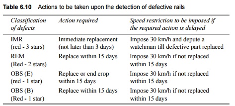
The actions to be taken upon the detection of defective rails
are summarized in Table 6.10.
Table 6.10 Actions to be taken upon
the detection of defective rails
In the case of OBS rails other than OBS (E) and
OBS (D), permanent way inspector (PWI) should observe each OBS location with a
magnifying glass and duly record his observations once a month, to see if the
crack has developed any further, in which case the same action as for REM
defects should be taken. The PWI should maintain sleepers, fittings, and the
ballast at such locations in sound condition. The assistant engineer should
also test-check some of the OBS locations and record his observations during
his monthly push trolley inspection of each section.
4 Ultrasonic Rail Flaw Testing Car
As the portable ultrasonic rail
flaw detector can test only 2-3 km of rails everyday, advanced railways such as
German Railways have developed a rail testing car that can test a much
longer length of track much more effectively. The test car tests the track at a
speed of 30 kmph and each of the two rails is tested ultrasonically by means of
five probes (0 o , �35 o , �70 o ) and an airborne sound assembly. The test results
are recorded photographically on a tape, a subsequent examination of which can
reveal all the flaws. The flaws can then be properly classified. Their position
in the track can also be pinpointed with respect to kilometrage to an accuracy
of 1 m. This special car tests the track during the day and covers 100-200 km
per day. The car covers approximately 20,000 km of track every year on German
Railways. The average cost of testing is Rs 300-500 per km of the track. With
the present trend in increase in speed, the need for ultrasonic inspection of
rails is felt all the more to avoid hazards due to rail fractures, and in this
context, the use of the test car on Indian Railways is considered a technical
and operational necessity.
5 Self-propelled Ultrasonic Rail Testing
Car
Indian Railways has recently
procured a self-propelled ultrasonic rail testing (SPURT) car of make
MATRIX-VUR-404 from Sa Matrix Industries, Paris, at a total cost of
approximately Rs 25 million, inclusive of ancillary equipment. The MATRIX car
is capable of detecting, measuring, recording, and simultaneously analysing the
internal defects of rails using a non-destructive method of rail flaw detection.
The rail testing car has been designed for simultaneous examination of rails,
points, and crossings at a maximum speed of 40 kmph. It consists of the
following parts.
(a) An
ultrasonic detection lorry
(b) An
electronic unit including all circuit transmitters, receivers, selectors, and
auxiliaries
(c) Two
multi-track recorders installed at either end of the car
(d) A
real-time automatic defect analyser
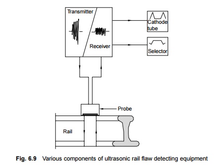
The various components of rail flaw detecting equipment are
shown in the schematic diagram in Fig. 6.9. Testing is done using five probes
at different angles, which are able to detect rail flaws.
The SPURT car can detect most
rail defects that normally develop under traffic during service. The type of
defect, its size, and its position in the rail section is automatically
determined. The SPURT car is able to screen the rail section completely in the
web and almost completely in the head and the zone of the foot below the web.
The flange of the foot and the top corners of the head, however, are not
screened. The defects recorded are automatically analysed. The results are
given in a synthesized form in a prescribed manner.
It is expected that the SPURT car will be used intensively on
Indian Railways and that it will be possible to control rail fractures/failures
on Indian Railways to a considerable extent.
6 Need-based Concept of
USFD Testing
Indian Railways has decided to introduce on its system a
need-based concept of USFD testing based on a Russian concept. As per the
present policy, need-based rail inspection is being progressively introduced on
A (not covered by the SPURT car), B, and D routes on Indian Railways. The
introduction of this concept will require changing the present classification
of defects, frequency of inspection, detection equipment, organization, etc.
The following are the important features of the
need-based scheme of USFD testing.
Traffic density and periodicity In the
need-based concept, the stipulated frequency of ultrasonic inspection is
one after the passage of every 8 GMT, with periodicity varying from 2 to 6
months, depending on the sectional GMT.
Important related parameters The
system has been evolved based on the consideration of two important
related parameters: permissible condemning defects size and inspection
frequency. Other important factors such as microstructure of rail steel and
nature and orientation of cracks, have not been taken into consideration.
Defect size Under the
concept, a defect size of 12 mm and above in the head and 5 mm and above
in the web junction is taken into account for the classification of defects.
Therefore, defects sized below 12 mm and 5 mm are allowed to continue in the
tracks as unclassified defects. Further, the same size of artificial flaw,
i.e., 12 mm, is considered when classifying the weld defect too. Attenuation or
absorption of ultrasonic energy is supposed to be more in SKV/AT welded joints
due to coarse grain, whereas absorption of energy is less in rail steel. (SKV
is a German word meaning short preheating. AT denotes alumino thermit.)
Obviously, the specified 60% peak height will not be available in the same
grain setting in the case of welds.
Frequency of testing of rails and welds An
inspection frequency of 8 GMT has been prescribed for the need-based
concept of ultrasonic testing. A higher inspection frequency may be fixed
depending upon the incidence of defects. In view of this, whenever the defect
generation rate (failures in service and defects detected during USFD
inspection) exceeds 1 per km between successive tests in a stretch, the
inspection frequency should be doubled in that particular stretch. When
calculating the defect generation rate, only rail defects (IMR) or fractures
with an apparent origin other than the bolt area and detectable by USFD should
be considered.
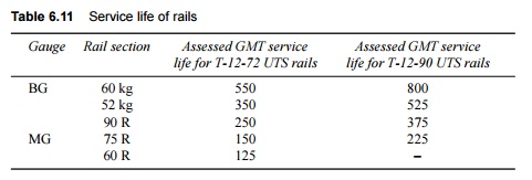
Testing of rails After the
initial testing of rails in the rail manufacturing plant, the first
re-test normally need not be done until the rails have covered 15% of their
service life in GMT as given in Table 6.11. For rails rolled in April 1999 and
later, the test-free period will be 25% instead of 15%.
Table 6.11 Service life of rails
Whenever rails are not tested in
the rail manufacturing plant, the test-free period will be applicable, and rail
testing will be done at the periodic interval given in Table 6.12 right from
the day of its laying in the field. This table gives the frequency of
ultrasonic testing after the passage of 8 GMT, subject to a maximum interval of
one year.
Table 6.12 Frequency of ultrasonic
testing for all BG routes

In the need-based concept, the
actions suggested in Table 6.13 are taken when defective rails are detected.
Table 6.13 Action to be taken after
detection of rail/weld defects

Related Topics