Chapter: Basic Radiology : Radiology of the Chest
Radiology of the Chest: Techniques
TECHNIQUES
Conventional Radiography
The Posteroanterior and Lateral Chest Radiograph
The simplest conventional study
of the chest is a posteroan-terior and lateral chest radiograph taken in a
radiographicunit specially designed for these studies. The x-rays travel
through the patient and expose a receptor from which the image is recorded. Most
commonly, digital receptors are used, although a receptor utilizing an
intensifying screen and radiographic film remains in some use as well.
Com-puted radiography and large field-of-view image intensi-fiers are two types
of digital receptors. The digital images may be printed on film by laser
printers but are generally viewed on monitors. The two views of a chest
radiograph are taken in projections at 90 degrees to each other with the
patient’s breath held at the end of a maximum inspira-tion. The first view is
obtained as the patient faces the re-ceptor with the x-ray beam source
positioned 6 feet behind him. Because the x-ray beam travels in a
posterior-to-anterior direction, this view is called a posteroanterior (PA)
chest radiograph. Another view is then obtained with the patient turned 90
degrees and the left side against the receptor and arms overhead. The x-ray
beam travels from right to left through the patient, and this is called a left
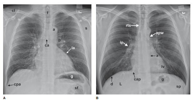
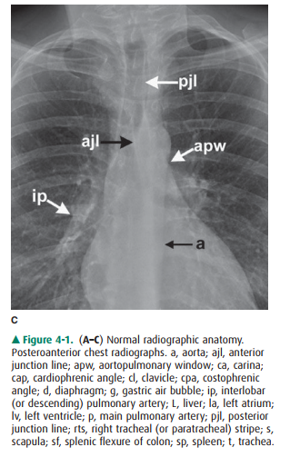
lat-eral view. Anatomic features of the chest that are readily identifiable on
conventional radiographs are shown in Figures 4-1 and 4-2.
Other Radiographic Projections
In some clinical situations,
patients may not be able to stand or sit upright for the conventional PA and
lateral ra-diographs, and an image must be taken with the patient’s back turned
to the receptor and the x-ray beam traversing the patient in an
anterior-to-posterior direction. These ra-diographs are called anteroposterior
(AP) radiographs. They may be taken in the x-ray department but are more
commonly obtained as portable studies at the patient’s bedside.
Images may also be obtained with
the patient lying on one side in a decubitus position with the x-ray beam
tra-versing the patient either PA or AP along a horizontal plane. These images
are designated as lateral decubitus im-ages (see Figure 4-63c). A left lateral
decubitus radiograph indicates that the left side of the patient is dependent
against the table. A right lateral decubitus radiograph indi-cates that the
right side of the patient is dependent against the table.
The Portable Chest Radiograph
If the clinical situation
prevents the patient from coming to the radiology department, a chest
radiograph may be ob-tained at the patient’s bedside, and these are almost
always AP radiographs. The AP portable radiograph does not pro-vide as much
information as PA and lateral chest radi-ographs for a number of reasons.
Because it is a single view, lesions are not as easily or accurately localized
along the AP axis of the thorax. The patients for whom these images areobtained
are usually quite ill and cannot be positioned as well as patients traveling to
the x-ray department. An ill pa-tient may not be able to cooperate by holding
his breath at full inspiration. A mobile x-ray generator is typically not as
powerful as a fixed x-ray generator, and longer exposure times therefore are
necessary to obtain sufficient exposure. The quality of portable chest
radiographs, therefore, is often inferior to that of PA and lateral
radiographs, as a result of both respiratory and cardiac motion. X-ray grids
are used to reduce scatter radiation and improve image quality. Grids are used
for most conventional chest radiographs done in radiology departments where
fixed equipment is present. Grids are not usually used for portable
radiographs, and the result is a high proportion of scattered x-rays, which
degrade the image. Paradoxically, the portable radiograph may be more expensive
than a conventional PA and lateral chest ra-diograph, owing to extra labor and
equipment costs in ob-taining a bedside radiograph.
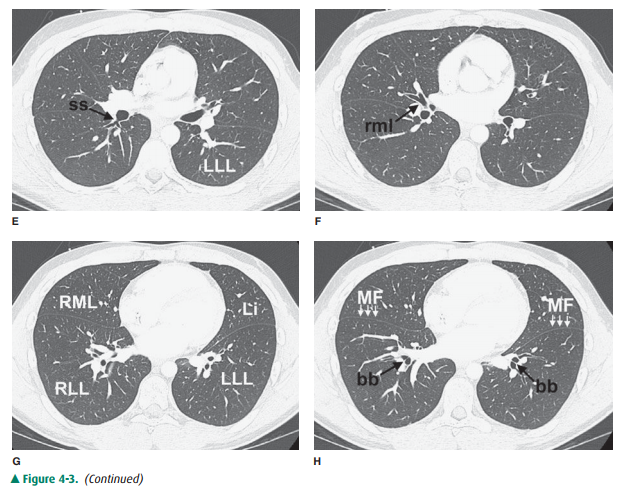
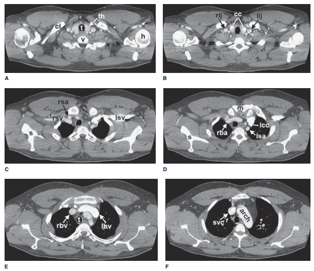
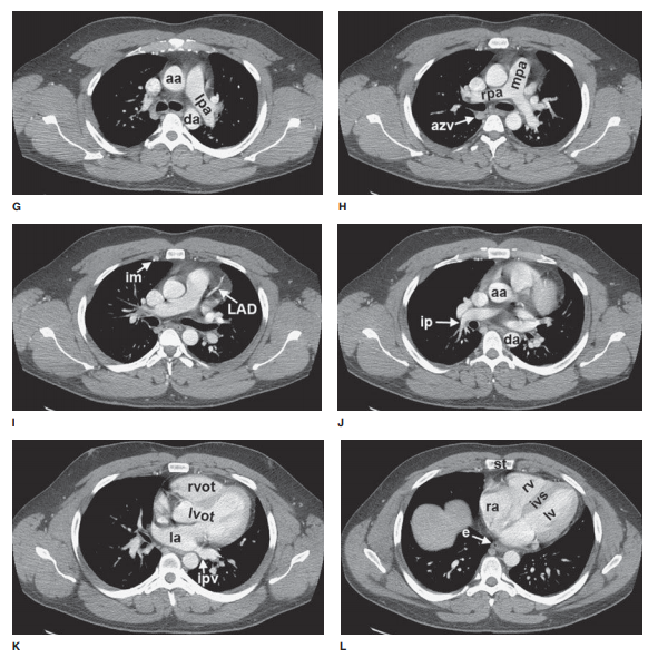
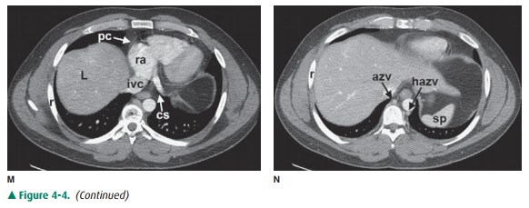
Computed Tomography of the Chest
For CT examinations of the chest,
intravenous contrast ma-terial is frequently administered for opacification of
arteries and veins within the mediastinum and hila to facilitate the
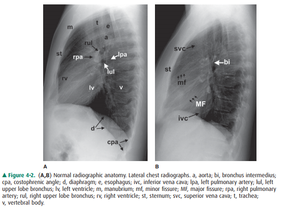
recognition of abnormal masses or lymph nodes. Anatomic features of the chest
that are readily identifiable on CT scans are shown in Figures 4-3 and 4-4.
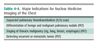
Nuclear Medicine Perfusion Imaging of the Chest
Nuclear medicine techniques used
in evaluating diseases of the thorax include ventilation-perfusion (V/Q) scanning
and scanning with tumor-seeking radiopharmaceuticals for tumor staging. The V/Q
scan may be used for patients with suspected pulmonary thromboembolism and who
have con-trast allergy or renal failure. The V/Q scan is noninvasive, and when
results are negative, fewer than 10% of patients have pulmonary
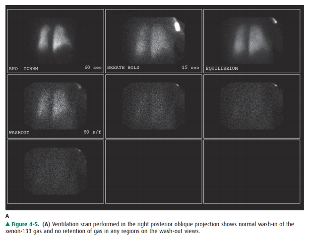
thromboembolism. The ventilation study is typi-cally performed with the patient
inhaling 10 to 30 mCi of xenon-133 while images are obtained with a
scintillation camera (Figure 4-5A). Wash-in images are obtained for two
consecutive 120-second periods, an equilibrium image is ob-tained, and then
wash-out images are obtained over 30- to 60-second periods in posterior and
left and right posterior oblique projections. This portion of the study takes
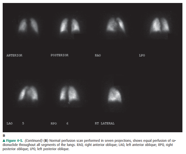
about 15 minutes. The perfusion scan is obtained by intravenously injecting 2
to 4 mCi of technetium-99m-labeled macroaggre-gated albumin containing 200,000
to 700,000 particles. The particles range in size from 10 to 100 m, and they
lodge in capillaries and capillary arterioles, accurately reflecting pul-monary
blood flow (Figure 4-5B). The scintillation camera is set so that it obtains
anterior, posterior, both posterior oblique, and both anterior oblique
projections for 750,000 counts per image. The perfusion study takes about 30
minutes to perform.
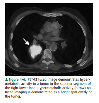
Positron Emission Tomography/Computed
Tomography Imaging of the Chest
Tomography is also available for
radionuclide imaging. A PET scanner resembles a CT scanner and uses positron
emitters (fluorine-18 [F-18] or carbon-11 [C-11]). Today, the most widely used
positron emitter is F-18-fluoro-deoxyglucose (FDG), which is used as a
metabolic tracer. The raised metabolic rate can be used to distinguish
neo-plasm and inflammation from normal tissue. Although PET provides
tomographic images, the spatial resolution (0.7 to 1.0 cm) is somewhat inferior
to that of CT. This spatial res-olution is improved by utilizing PET/CT fusion
imaging in which a patient receives both a PET scan with F-18 FDG as well as a
CT with or without contrast. These images can then be overlaid, or fused
(Figure 4-6), to combine the spa- tial resolution of CT with the localization
power of ra-dionuclide imaging.
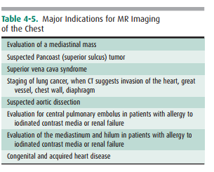
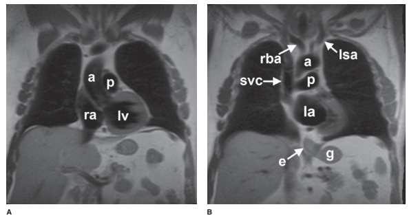
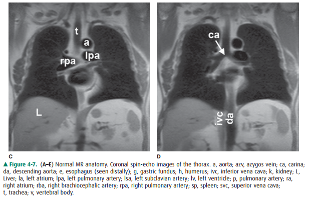
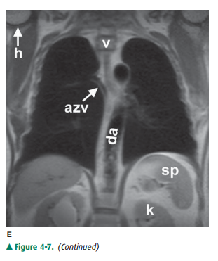
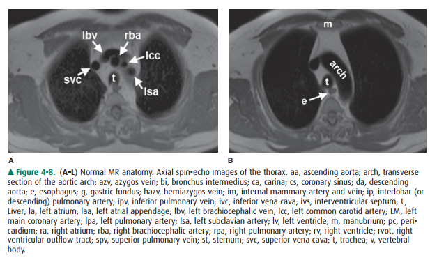
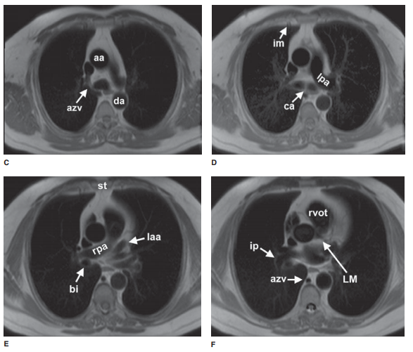
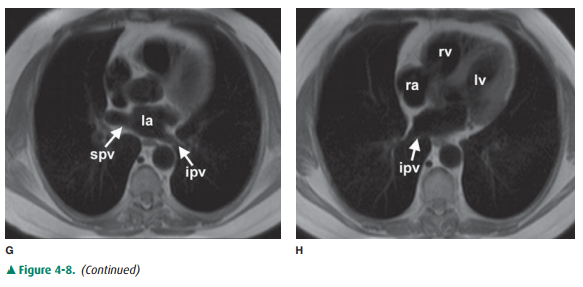
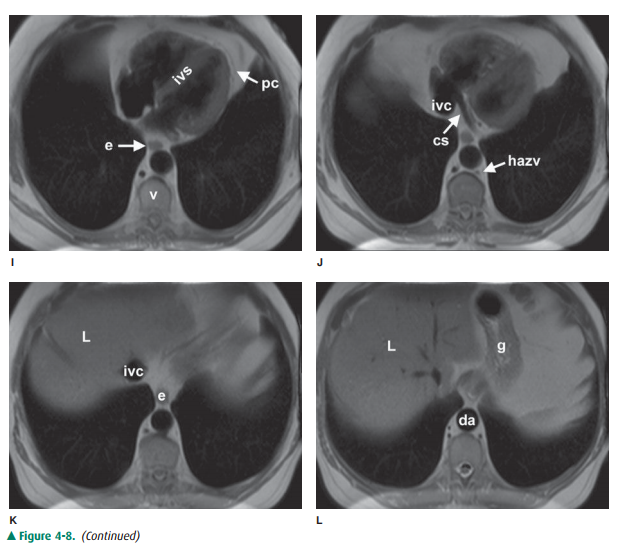
Magnetic Resonance Imaging of the Chest
The principles and applications
of MR are described earily. Anatomic features of the chest that are readily
identifiable on MR images are shown in Figures 4-7 and 4-8.
Ultrasonography of the Chest
Ultrasound is described in detail
in earily. Ultrasound of the chest is typically performed to evaluate fluid
collections within the pleural space. Ultrasound may be used to guide
thoracentesis, especially when the fluid collection is small or loculated. Less
frequently, ultrasound is utilized to guide per-cutaneous biopsy of mediastinal
or peripleural lung lesions. Advances in image fusion also allow fusion of
ultrasound im-ages with a separately performed CT examination, which can be
useful for ultrasound-guided biopsies in the thorax.
Related Topics