Chapter: Electrical Engineering and Instrumentation : Analog and Digital Instruments
Q-Meter
Q-Meter
Every
inductor coil has a certain amount of resistance and the coil should have
lowest possible resistance. The ratio of the inductive reactance to the
effective resistance of the coil is called the quality factor or Q-factor of
the coil. So Q = XL/ R = ωL /
R
A high
value of Q is always desirable as it means high inductive reactance and low
resistance. A low value of Q indicates that the resistance component is
relatively high and so there is a comparatively large loss of power.
The
effective resistance of the coil differs from its dc resistance because of eddy
current and skin effects and varies in a highly complex manner with the
frequency. For this reason Q is rarely computed by determination of R and L
One
possible way for determination of Q is by using the inductance bridge but such
bridge circuits are rarely capable of giving accurate measurements, when Q is
high. So special meters are used for determination of Q accurately.
The
Q-meter is an instrument designed for the measurement of Q-factor of the coil
as well as for the measurement of electrical properties of coils and
capacitors. -This instrument operates on the principle of series resonance i.e.
at resonate condition of an ac series circuit voltage across the capacitor is
equal to the applied voltage times of Q of the circuit. If the voltage applied across
the circuit is kept-constant then voltmeter connected across the capacitor can
be calibrated to indicate Q directly.
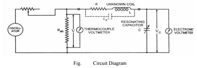
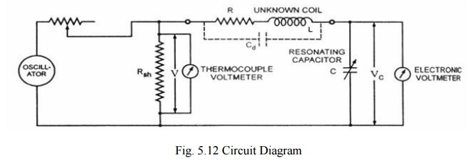
Circuit
diagram of a Q-meter is shown is figure. A wide-range oscillator with frequency
range from 50 kHz to 50 MHz is used as a power supply to the circuit. The
output of the oscillator is shorted by a low-value resistance, Rsh
usually of the order of 0.02 ohm. So it introduces almost no resistance into
the oscillatory circuit and represents a voltage source with a very small or of
almost negligible internal resistance. The voltage across the low-value shunt
resistance Rsh, V is measured by a thermo-couple meter and the
voltage across the capacitor, Vc is measured by an electronic
voltmeter.
For
carrying out the measurement, the unknown coil is connected to the test
terminals of the instrument, and the circuit is tuned to resonance either by
varying the frequency of the oscillator or by varying the resonating capacitor
C. Readings of voltages across capacitor C and shunt resistance Rsh are
obtained and Q-factor of the coil is determined as follows :
By
definition Q-factor of the coil, Q = XL/
R
And when
the circuit is under resonance condition XL=
XCOr IXL= IXC= VC
And the
voltage applied to the circuit. V = IR
So, Q = XL/ R = IXL/
R = VC/ V This Q-factor is called the circuit Q because this
measurement includes the losses of the resonating capacitor, voltmeter and the
shunt resistor Rsh. So, the actual Q-factor of the coil will be
somewhat greater
than the
calculated Q-factor. This difference is usually very small and maybe neglected
except when the resistance of the coil under test is relatively small in
comparison to the shunt resistance Rsh. The inductance of the coil
can also be computed from the known values of frequency f and resonating
capacitor C as follows. At resonance, XL=
XCor 2Ď€fL = 1/2Ď€fC or L = 1/ (2Ď€f)2 Henry.
Related Topics