Chapter: mechanical : Engineering Graphics
Projection of Solids and Section of Solids
PROJECTION OF SOLIDS AND SECTION OF SOLIDS
Projections of prism, pyramid, cone and cylinder, axis inclined to one plane by change of position method. Section of above solids in simple vertical position (axis perpendicular to HP alone) by planes either inclined to HP or VP alone- True shape of section.
PROJECTION OF SOLIDS AND SECTION OF SOLIDS
Projection of Solids:
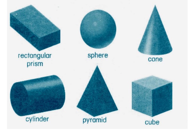
A solid is a three dimensional object having length, breadth and thickness. It is Completely bounded by a surface or surfaces, which may be curved or plane. The shape of a solid is described orthographically by drawing its two orthographic projections, usually, on the two principal planes of projection i.e., HP and VP.
The following are the different positions which the axis of a solid can take with respect to the reference planes:
1. Axis perpendicular to HP and parallel to VP.
(CONE AND PYRAMID)
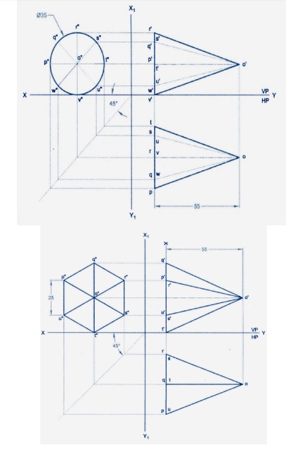
2. Axis perpendicular to VP and parallel to HP
(PYRAMID, CONE, PRISM)
3. Axis parallel to both HP and VP, i.e., axis perpendicular to a profile plane.
4. Axis inclined to HP and parallel to VP.
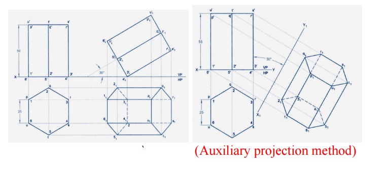
(Auxiliary projection method)
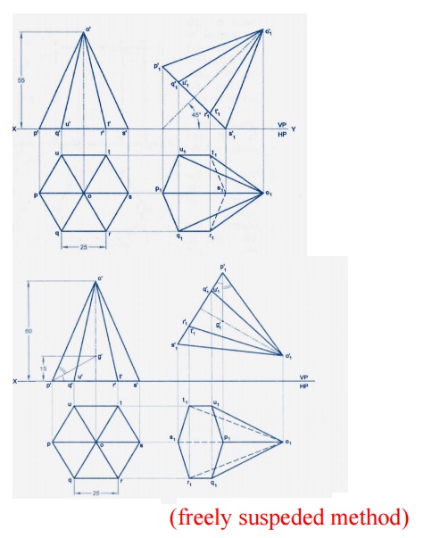
(freely suspeded method)
5. Axis inclined to VP and parallel to HP.
6. Axis inclined to both HP and VP. (Not For University Syllabus)
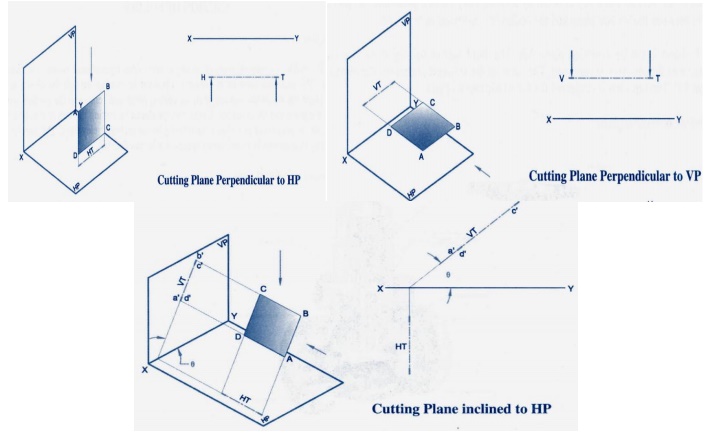
SECTION OF SOLIDS:
The hidden or internal parts of an object are shown by sectional views in technical drawings. The sectional view of an object is obtained by cutting through the object by a Suitable plane known as the section plane or cutting plane and removing the portion lying between the plane and the observer. The surface produced by cutting the object is called the section and its projection is called a sectional plan or sectional elevation. The section is indicated by thin section lines uniformly spaced and inclined at 45°.
A sectional view of an object is obtained by projecting the retained portion of the Jet which is left behind when object is cut by an imaginary section plane and the portion the object between the section plane and the observer is assumed as removed.
The object is cut by a section plane AA. The front half of the object between the Section plane and the observer are removed. The view of the retained portion of the object is projection VP. The top view is projected for the whole uncut object.
Types of sectional views of solids:
By using the five different types of perpendicular section planes we .obtain the following five types of sectional views of solids:
1. Section of solids obtained by horizontal planes.
2. Section of solids obtained by vertical planes.
3. Sections of solids obtained by auxiliary inclined planes.
4. Section of solids obtained by auxiliary vertical planes.
5. Section of solids obtained by profile planes.

Important Questions
1. A tetrahedron of edges 30mm rests on one of its edges on the VP. That edges is normal to the hp. one of the faces containing the resting edge is inclined at 30oto the VP. Draw the projections of the tetrahedron.
2. A cube of 70mm long edges has its vertical faces equality inclined to the VP. It is cut by an auxiliary inclined plane in such a way that the true shape of the cut part is a regular hexagon. Determine the inclination of the cutting plane with the HP. Draw front view, sectional top view and true shape of the section.
3. A regular pentagonal lamina ABCDF of side 30mm has one of its edges parallel to the VP and inclined at 30® to the HP. The pentagon is inclined 45®to the VP. Draw projections.
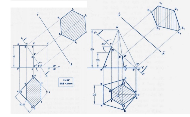
4. A pentagonal prism of 30-mm side of base and 70mm height is resting on one of its edges of the base in such a way that the base makes an angels of 45® HP, and the axis is parallel to VP. Draw the projections of the prism.
5. Draw the top front views of a right circular cylinder of base 45mm diameter and 60mm long when it line on HP, such that its axis is inclined at 30® to HP and the axis appears to parallel to the VP in the top view.
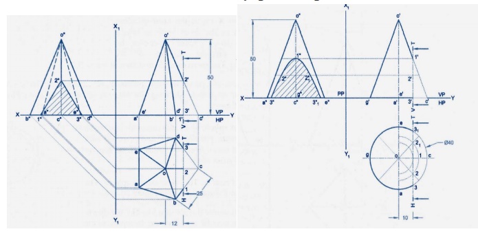
6. Draw the projection of a cylinder of diameter 40mm and axis 70mm long when it rests on the VP on one of its base points. The axis if cylinder is parallel to VP and inclined at 30® to VP.
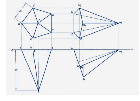
7. A hexagonal pyramid of bases side 30mm and axis length 60mm is resting on VP one of its base edges with the face containing the resting edges perpendicular to both HP and VP. Draw its projections.
8. A cone of base diameter 60mm and axis 70mm is resting on HP on its base. It is cut by a plane perpendicular to VP and parallel to a contour generator and is10mm away from it. Draw the front view, sectional top view and the true shape of the section.
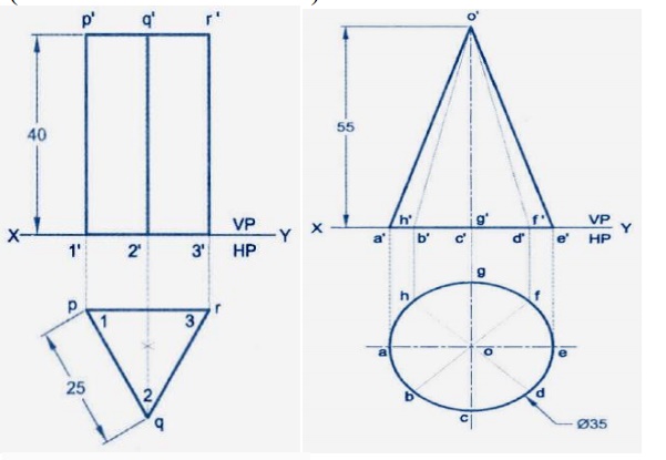
9. An equilateral triangular prism 20mm side of base and 50mm long rests with one of its shorter edges on HP such that the rectangular face containing the edge on which the prism rests is inclined at 30® to HP. This shorter edge resting on HP is perpendicular to VP.
10. A square pyramid of base 40mm and axis 70mm lone has one of its triangular faces on VP and the edge of base contained by that face is perpendicular to VP. Draw its projections.
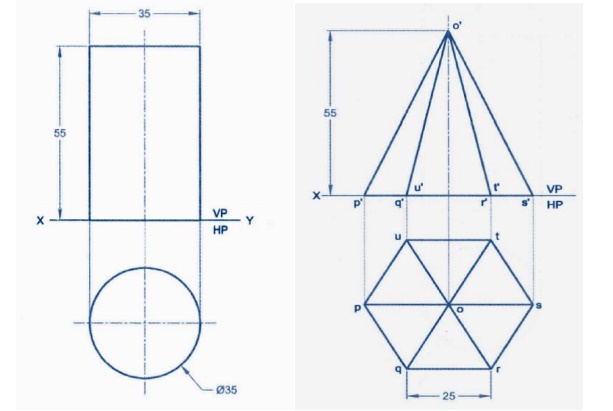
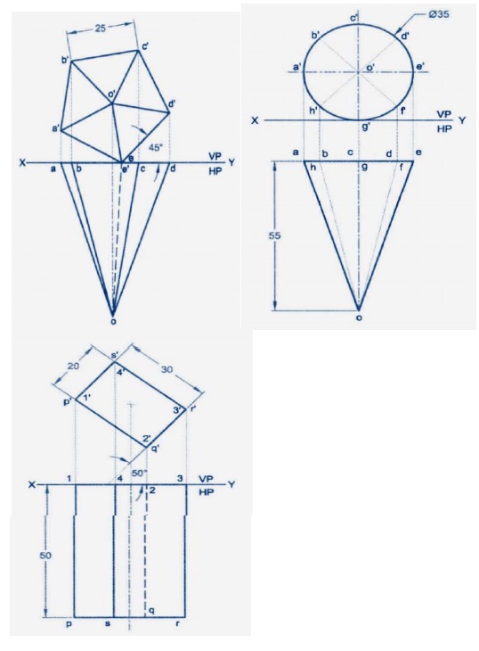
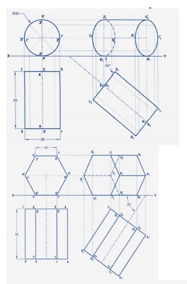
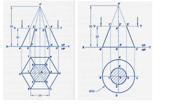
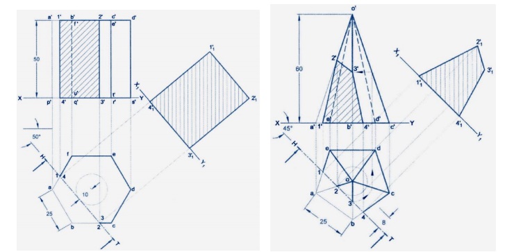
11. A hexagonal prism of side of base 35mm and axis length 55mm rests with its base on HP such that two of the vertical surfaces are perpendicular to VP. It is cut by a plane inclined at 50® to HP and perpendicular to VP and passing through a point an the axis at a distance 15mm from the top. Draw its front view, sectional top view and true shape of section.
12. An equilateral triangular prism 20mm side of base and 50mm rests with are of its shorter edges on H.P. such that the rectangular face containing the edge on which the prism rests is inclined at30 to H.P. the shorter edge resting on HP is perpendicular to VP.
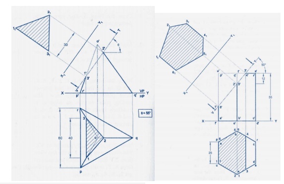
13. Draw the projections of a hexagonal pyramid with side of the base 30mm and axis on HP such that the triangular face containing that side is perpendicular to HP and axis is parallel to VP.
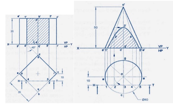
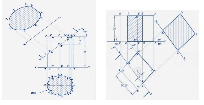
14. A vertical cylinder 40mm diameter is cut by a vertical section plane making 30 to VP in such a way that the true shape of the section is a rectangle of 25mm and 60mm side. Draw the projections and true shape of the section.
15. A tetrahedron of edges 30mm rests on one of its edges on the VP. That edge is normal to the HP. One of the faces containing the resting edge is inclined at30® to the VP. Draw the projections of the tetrahedron.
16. A cone of base diameter 60mm and altitude 80mm rests on the HP with its axis inclined at30® to the HP and parallel to the VP. Draw its front and top views.
Related Topics