Chapter: Embedded Systems
Programming Input and Output in Embedded Systems
PROGRAMMING INPUT AND OUTPUT
Then
basic techniques for I/O programming can be understood relatively independent
of the instruction set. In this section, we cover the basics of I/O programming
and place them in the contexts of both the ARM and begin by discussing the
basic characteristics of I/O devices so that we can understand the requirements
they place on programs that communicate with them.
INPUT AND OUTPUT DEVICES
Input and
output devices usually have some analog or non-electronic component— for
instance, a disk drive has a rotating disk and analog read/write electronics.
But the digital logic in the device that is most closely connected to the CPU
very strongly resembles the logic you would expect in any computer system.
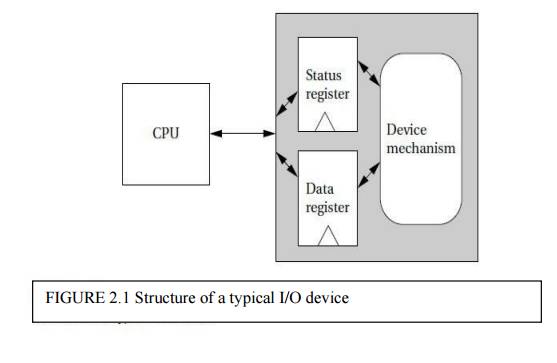
Figure
2.1 shows the structure of a typical I/O device and its relationship to the
CPU. The interface between the CPU and the device’s internals (e.g., the
rotating disk and read/write electronics in a disk drive) is a set of
registers. The CPU talks to the device by reading and writing the registers.
Devices
typically have several registers,
■ Data registers hold values that are treated as
data by the device, such as the data read
or written by a disk.
■ Status registers provide information about the
device’s operation, such as whether
the current transaction has completed.
Some
registers may be read-only, such as a status register that indicates when the
device is done, while others may be readable or writable. Application Example
2.1 describes a classic I/O device.
Application Example
The 8251
UART
The 8251 UART (Universal Asynchronous
Receiver/Transmitter) [Int82] is the original device used for serial
communications, such as the serial port connections on PCs. The 8251 was
introduced as a stand-alone integrated circuit for early microprocessors.
Today, its functions are typically subsumed by a larger chip, but these more
advanced devices still use the basic programming interface defined by the 8251.
The UART
is programmable for a variety of transmission and reception parameters.
However, the basic format of transmission is simple. Data are transmitted as
streams of characters, each of which has the following form:
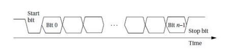
Every
character starts with a start bit (a 0) and a stop bit (a 1). The start bit
allows the receiver to recognize the start of a new character; the stop bit
ensures that there will be a transition at the start of the stop bit. The data
bits are sent as high and low voltages at a uniform rate. That rate is known as
the baud
rate; the period of one bit is the inverse of the baud rate.
Before transmitting or receiving data, the CPU must
set the UART’s mode registers to correspond to the data line’s characteristics.
The parameters for the serial port are familiar from the parameters for a
serial communications program (such as Kermit)
■ the baud
rate;
■ the
number of bits per character (5 through 8);
■ whether
parity is to be included and whether it is even or odd; and
■ the length of a stop bit (1, 1.5, or 2 bits).
The UART includes one 8-bit register that buffers
characters between the UART and the CPU bus. The Transmitter Ready output
indicates that the transmitter is ready to accept a data character; the
Transmitter Empty signal goes high when the UART has no characters to send. On
the receiver side, the Receiver Ready pin goes high when the UART has a
character ready to be read by the CPU.
INPUT AND OUTPUT PRIMITIVES
Microprocessors can provide programming support for
input and output in two ways: I/O instructions and
memory-mapped I/O. Some architectures, such as the Intel x86, provide special
instructions (in and out in the case of the Intel x86) for input and output.
These instructions provide a separate address space for I/O devices. But the
most common way to implement I/O is by memory mapping even CPUs that provide
I/O instructions can also implement memory-mapped I/O. As the name implies,
memory-mapped I/O provides addresses for the registers in each I/O device.
Programs use the CPU’s normal read and write instructions to communicate with
the devices. Example 3.1 illustrates memory-mapped I/O on the ARM.
Example
Memory-mapped
I/O on ARM
We can
use the EQU pseudo-op to define a symbolic name for the memory location of our
I/O device:
DEV1 EQU
0x1000
Given that name, we can use the following standard
code to read and write the device register:
Read DEV1
LDR r0,
#8 ; set up value to write
STR r0, [r1] ;
write 8 to device
How can
we directly write I/O devices in a high-level language like C? When we define
and use a variable in C, the compiler hides the variable’s address from us. But
we can use pointers to manipulate addresses of I/O devices. The traditional
names for functions that read and write arbitrary memory locations are peek
and poke.
The peek
function can be written in C as:
int
peek(char *location) {
return
*location; /* de-reference location pointer */
}
The
argument to peek is a pointer that is de-referenced by the C * operator to read
the
location. Thus, to read a device register we can
write: #define DEV1 0x1000
dev_status
= peek(DEV1); /* read device register */
The poke
function can be implemented as:
void
poke(char *location, char newval) { (*location) = newval;
/* write
to location */
}
To write to the status register, we can use the
following code: poke(DEV1,8);
/*write 8
to device register */
These
functions can, of course, be used to read and write arbitrary memory locations,
not just devices
BUSY-WAIT I/O
The most basic way to use devices in a program is busy-wait
I/O. Devices are typically slower than the CPU and may require many
cycles to complete an operation. If the CPU is performing multiple operations
on a single device, such as writing several characters to an output device,
then it must wait for one operation to complete before starting the next one.
(If we try to start writing the second character before the device has finished
with the first one, for example, the device will probably never print the first
character.) Asking an I/O device whether it is finished by reading its status
register is often called polling.
Example
illustrates busy-wait I/O.
Busy-wait
I/O programming
In this
example we want to write a sequence of characters to an output device. The
device has two registers: one for the character to be written and a status
register. The status register’s value is 1 when the device is busy writing and
0 when the write transaction has completed.
We will use the peek and poke functions to write
the busy-wait routine in C. First, we define symbolic names for the register
addresses:
#define
OUT_CHAR 0x1000 /* output device character register */ #define OUT_STATUS
0x1001 /* output device status register */
The sequence of characters is stored in a standard
C string, which is terminated by a null (0) character. We can use peek and poke
to send the characters and wait for each transaction to complete:
char
*mystring = "Hello, world." /* string to write */ char *current_char;
/* pointer to current position in
string*/
current_char
= mystring; /* point to head of string */ while (*current_char != `\ 0') { /*
until null character */
poke(OUT_CHAR,*current_char);
/* send character to device */
while
(peek(OUT_STATUS) != 0); /* keep checking status */
current_char++;
/* update character pointer */
}
The outer while loop sends the characters one at a
time. The inner while loop checks the device status—it implements the busy-wait
function by repeatedly checking the device status until the status changes to
0.
Example
Copying
characters from input to output using busy-wait I/O
We want
to repeatedly read a character from the input device and write it to the output
device. First, we need to define the addresses for the device registers:
#define
IN_DATA 0x1000 #define IN_STATUS 0x1001 #define OUT_DATA 0x1100 #define
OUT_STATUS 0x1101
The input
device sets its status register to 1 when a new character has been read; we
must set the status register back to 0 after the character has been read so
that the device is ready to read another character. When writing, we must set
the output status register to 1 to start writing and wait for it to return to
0. We can use peek and poke to repeatedly perform the read/write operation:
while
(TRUE)
{ /*
perform operation forever */ /* read a character into achar */
while
(peek(IN_STATUS) == 0); /*wait until ready*/ (char)peek(IN_DATA); /* read the
character achar*//* write poke(OUT_DATA,achar);poke(OUT_STATUS,1); /* turn on
device */ while(peek(OUT_STATUS) != 0); /*wait until done*/}
Related Topics