Chapter: civil : Applied Hydraulic Engineering: Gradually Varied Flow
Profile Classifications
Civil - Applied Hydraulic Engineering: Gradually
Varied Flow
Profile Classifications
Before
attempting to solve the gradually varied flow equation a great deal of insight
into the type of solutions and profiles possible can be gained by taking some
time to examine the equation.
Time
spent over this is almost compulsory if you are to understand steady flow in
open channels. For a given discharge, S f and Fr2 are functions of depth.
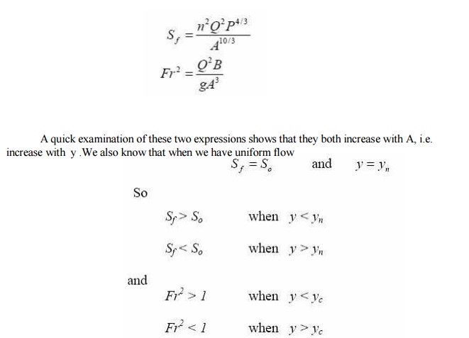
From
these inequalities we can see how the sign of dy/dx i.e. the surface slope
changes for different slopes and Froude numbers.
Taking
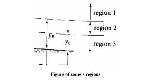
the example of a mild slope, shown in the figure below:

The normal and critical depths
are shown (as it is mild normal depth is greater than critical depth). Treating
the flow as to be in three zones:
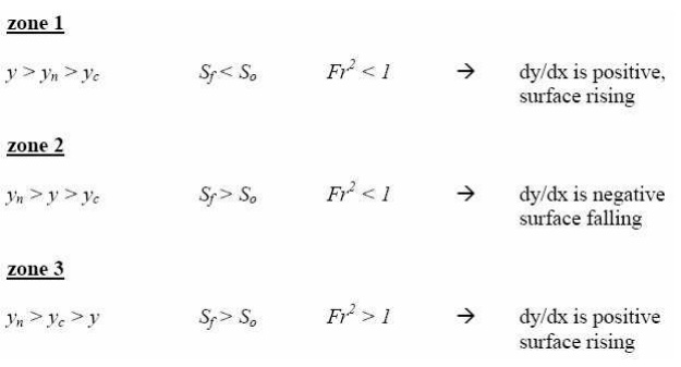
i. zone 1,
above the normal depth
zone 2,
between normal and critical depth iii. zone 3, below critical depth The
direction of the surface inclination may thus be determined.
The condition at the boundary of
the gradually varied flow may also be determined in a similar manner:
zone 1
As y Q then S f
and Fr 0 and dy/dx S o
Hence the
water surface is asymptotic to a horizontal line for it maximum
As y y n
then S f S o and dy/dx 0
Hence the
water surface is asymptotic to the line y = y n i.e. uniform flow.
zone 2
As
for zone 1 as y approached the normal depth: As
y y n then S f
S o and
dy/dx 0
Hence the water surface is asymptotic to the line y = y n
But a problem occurs when y approaches the critical depth: As
y y c
then Fr 1 and dy/dx 8
This is physically impossible but
may be explained by the pointing out that in this region the gradually varied
flow equation is not applicable because at this point the fluid is in the
rapidly varied flow regime.
In
reality a very steep surface will occur.
zone 3
As
for zone 2 a problem occurs when y approaches the critical depth: As yy c then
Fr 1 and
dy/dx 8
Again we have the same physical
impossibility with the same explanation. And again in reality a very steep
surface will occur.
As y 0 then dy/dx
S o the slope of bed of the
channel !
The
gradually varied flow equation is not valid here but it is clear what occurs.
In general, normal depth is
approached asymptotically and critical depth at right angles to the channel
bed.
The
possible surface profiles within each zone can be drawn from the above
considerations. These are shown for the mild sloped channel below.
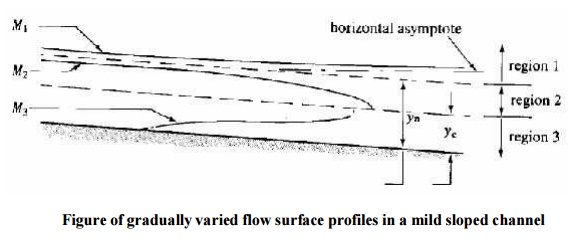
The surface profile in zone 1 of
a mild slope is called an M1 curve, in zone 2 an M2 curve and in zone 3 an M3
curve.
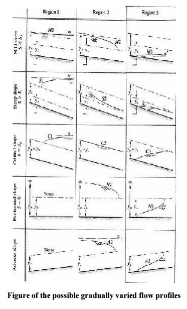
All the
possible surface profiles for all possible slopes of channel (there are 15
possibilities) are shown in the figure.
Related Topics