Chapter: Special Electrical Machines : Synchronous Reluctance Motors
Phaser Diagram of Synchronous Reluctance Motor
PHASER DIAGRAM OF SYNCHRONOUS
RELUCTANCE MOTOR
The
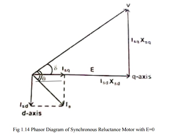
synchronous reluctance machine is considered as a balanced three phase circuit,
it is sufficient to draw the phasor diagram for only one phase. The basic
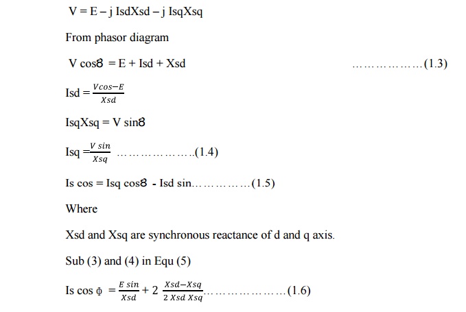
voltage equation neglecting the effect of resistance is
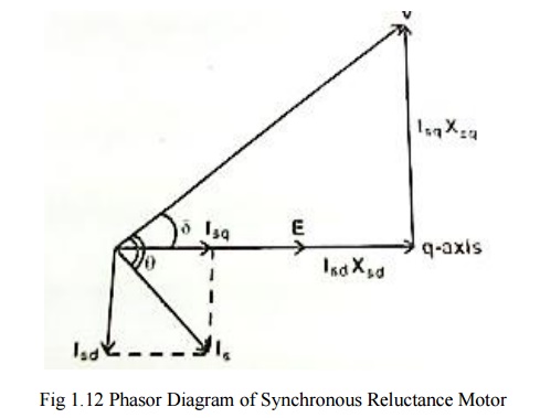
V = E – j
IsdXsd – j Isq…………(1.1)
Where
V is the
Supply Voltage
Is is the
stator current
E is the
excitation emf
Ȣ is the
load angle
ɸ is the
phase angle
Xsd and
Xsq are the synchronous reactance of direct and quadrature axis
Isd and
Isq are the direct and quadrature axis current
I = Isd +
Isq…………….(1.2)
Isd is in
phase quadrtur with E and Isq is in phase with E.
V = E – j
IsdXsd – j IsqXsq
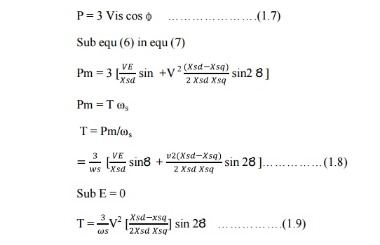
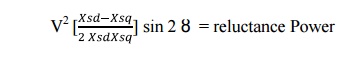
Equation
(9) is the torque equation of synchronous reluctance motor.
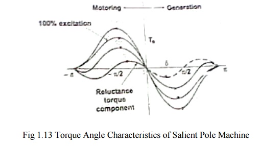
Plotting
the equation (9) as shown in fig indicates that the stability limit is reached
at Ȣ =± ᴨ /4
And by
increasing g load angle torque also increases.
In
synchronous reluctance motor, the excitation emf(E) is zero.
Related Topics