Chapter: High Voltage Engineering : Measurement of High Voltage and High Currents
Peak Voltmeters with Potential Dividers
Peak Voltmeters with Potential
Dividers
Passive
circuits are not very frequently used these days for measurement of the peak
value of a.c. or impulse voltages. The development of fully integrated
operational amplifiers and other electronic circuits has made it possible to
sample and hold such voltages and thus make measurements and, therefore, have
replaced the conventional passive circuits. However, it is to be noted that if
the passive circuits are designed properly, they provide simplicity and
adequate accuracy and hence a small description ofthese circuits is in order.
Passive circuits are cheap, reliable and have a high order of electromagnetic
compatibility. However, in contrast, the most sophisticated electronic
instruments are costlier and their electromagnetic compatibility (EMC) is low.
The passive circuits cannot measure high voltages directly and use potential
dividers preferably of the capacitance type. Fig. 4.4.1 shows a simple peak
voltmeter circuit consisting of a capacitor voltage divider which reduces the
voltage V to be measured to a low voltage Vm.
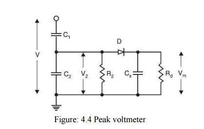
Suppose R2
and Rd are not present and the supply voltage is V. The voltage across the
storage capacitor Cs will be equal to the peak value of voltage across C2
assuming voltage drop across the diode to be negligibly small. The voltage
could be measured by an electrostatic voltmeter or other suitable voltmeters
with very high input impedance. If the reverse current through the diode is
very small and the discharge time constant of the storage capacitor very large,
the storage capacitor will not discharge significantly for a long time and
hence it will hold the voltage to its value for a long time. If now, V is
decreased, the voltage V2 decreases proportionately and since now
the voltage across C2 is smaller than the voltage across Cs to which
it is already charged, therefore, the diode does not conduct and the voltage
across Cs does not follow the voltage across C2. Hence, a discharge
resistor Rd must be introduced into the circuit so that the voltage
across Cs follows the voltage across C2. From measurement point of
view it is desirable that the quantity to be measured should be indicated by
the meter within a few seconds and hence Rd is so chosen that RdCs
≈ 1 sec. As a result of this, following errors are introduced. With the
connection of Rd, the voltage across Cs will decrease continuously
even when the input voltage is kept constant. Also, it will discharge the
capacitor C2 and the mean potential of V2 (t) will gain a
negative d.c component. Hence a leakage resistor R2 must be inserted
in parallel with C2 to equalize these unipolar discharge currents.
The second error corresponds to the voltage shape across the storage capacitor
which contains ripple and is due to the discharge of the capacitor Cs. If the
input impedance of the measuring device is very high, the ripple is independent
of the meter being used. The error is approximately proportional to the ripple
factor and is thus frequency dependent as the discharge time constant cannot be
changed. If RdCs = 1 sec, the discharge error amounts to 1% for 50 Hz and 0.33%
for 150 Hz. The third source of error is related to this discharge error.
During the conduction time (when the voltage across Cs is lower than that
across C2 because of discharge of Cs through Rd) of the diode the
storage capacitor Cs is recharged to the peak value and thus Cs becomes
parallel with C2. If discharge error is ed, recharge error er is
given by

Hence Cs
should be small as compared withC2 to keep down the recharge error.
It has also been observed that in order to keep the overall error to a low
value, it is desirable to have a high value of R2. The same effect
can be obtained by providing an equalizing arm to the low voltage arm of the
voltage divider as shown in Fig. 4.4.2 This is accomplished by the addition of
a second network comprising diode, Cs and Rd for negative polarity currents to
the circuit shown in Fig.4.4.3 With this, the d.c currents in both branches are
opposite in polarity and equalize each other. The errors due to R2 are thus
eliminated. Rabus developed another circuit shown in Fig. 4.4.4 to reduce
errors due to resistances. Two storage capacitors are connected by a resistor
Rs within every branch and both are discharged by only one resistance Rd.
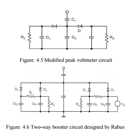
Here
because of the presence of Rs, the discharge of the storage capacitor Cs2
is delayed and hence the inherent discharge error is reduced. However, since
these are two storage capacitors within one branch, they would draw more charge
from the capacitor C2 and hence the recharge error would increase.
It is, therefore, a matter of designing various elements in the circuit so that
the total sum of all the errors is a minimum. It has been observed that with
the commonly used circuit elements in the voltage dividers, the error can be
kept to well within about 1% even for frequencies below 20 Hz. The capacitor C1
has to withstand high voltage to be measured and is always placed within the
test area whereas the low voltage arm C2 including the peak circuit
and instrument form a measuring unit located in the control area. Hence a
coaxial cable is always required to connect the two areas. The cable
capacitance comes parallel with the capacitance C2 which is usually
changed in steps if the voltage to be measured is changed. A change of the
length of the cable would, thus, also require recalibration of the system. The
sheath of the coaxial cable picks up the electrostatic fields and thus prevents
the penetration of this field to the core of the conductor. Also, even though
transient magnetic fields will penetrate into the core of the cable, no
appreciable voltage (extraneous of noise) is induced due to the symmetrical
arrangement and hence a coaxial cable provides a good connection between the
two areas. Whenever, a discharge takes place at the high voltage end of
capacitor C1 to the cable connection where the current looks into a
change in impedance a high voltage of short duration may be built up at the low
voltage end of the capacitor C1 which must be limited by using an
over voltage protection device (protection gap). These devices will also
prevent complete damage of the measuring circuit if the insulation of C1
fails.
Related Topics