Chapter: Microprocessor and Microcontroller
Operation in Multiprocessor mode in 8051
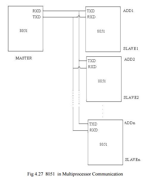
Operation in Multiprocessor mode :
8051
operates in multiprocessor mode for serial communication Mode-2 and Mode-3. In
multiprocessor mode, a Master processor can communicate with more than one
slave processors. The connection diagram of processors communicating in
Multiprocessor mode is given in fig 4.27.
The
Master communicates with one slave at a time. 11 bits are transmitted by the
Master, viz, One start bit (usually '0'), 8 data bits (LSB first), TB8 and a
stop bit (usually '1'). TB8 is '1' for an address byte and '0' for a data byte.
If the
Master wants to communicate with certain slave, it first sends the address of
the slave with TB8=1. This address is received by all the slaves. Slaves
initially have their SM2 bit set to '1'. All slaves check this address and the
slave who is being addressed, responds by clearing its SM2 bit to '0' so that
the data bytes can be received.
It should
be noted that in Mode 2&3, receive interrupt flag RI is set if REN=1, RI=0
and the following condition is true.
1. SM2=1 and
RB8=1 and a valid stop bit is received. Or
2. SM2=0 and
a valid stop bit is received.
After the
communication between the Master and a slave has been established, the data
bytes are sent by the Master with TB8=0. Hence other slaves do not respond /get
interrupted by this data as their SM2 is pulled high (1).
Power saving modes of operation :
8051 has
two power saving modes. They are -
1. Idle Mode
2. Power
Down mode.
The two
power saving modes are entered by setting two bits IDL and PD in the special
function register (PCON) respectively.
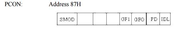
The
structure of PCON register is as follows. PCON: Address 87H
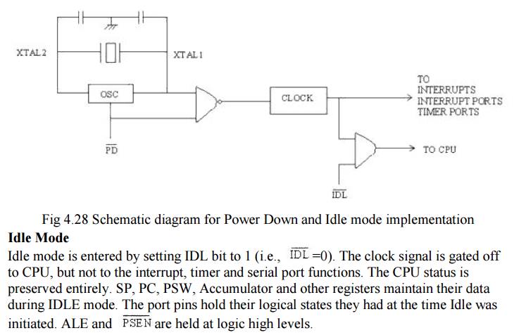
The
schematic diagram for 'Power down' mode and 'Idle' mode is given as follows:
Ways to exit Idle Mode:
1. Activation
of any enabled interrupt will clear PCON.0 bit and hence the Idle Mode is
exited. The program goes to the Interrupt Service Routine (ISR). After RETI is
executed at the end of the ISR, the next instruction will start from the one
following the instruction that enabled Idle Mode.
2. A
hardware reset exits the idle mode. The CPU starts from the instruction
following the instruction that invoked the 'Idle' mode.
Power Down Mode:
The Power
down Mode is entered by setting the PD bit to 1. The internal clock to the
entire microcontroller is stopped (frozen). However, the program is not dead.
The Power down Mode is exited (PCON.1 is cleared to 0) by Hardware Reset only.
The CPU starts from the next instruction where the Power down Mode was invoked.
Port values are not changed/ overwritten in power down mode. Vcc can
be reduced to as low as 2V in PowerDown mode. However, Vcc has to be
restored to normal value before PowerDown mode is exited.
Related Topics