Chapter: Basic Electrical and electronics : Electric Circuits and Measurements
Operating Principles of Moving Iron Instruments Ammeters and Voltmeters
Moving Iron instruments
Moving-iron
instruments are generally used to measure alternating voltages and currents. In
moving-iron instruments the movable system consists of one or more pieces of
specially-shaped soft iron, which are so pivoted as to be acted upon by the
magnetic field produced by the current in coil.
There are
two general types of moving-iron instruments namely:
1. Repulsion (or double iron) type (figure
1)
2. Attraction (or single-iron) type (figure
2)
The brief
description of different components of a moving-iron instrument is given below:
Moving element: A small piece of soft iron in
the form of a vane or rod.
Coil: To produce the magnetic field
due to current flowing through it and also to magnetize the iron pieces.
Repulsion type
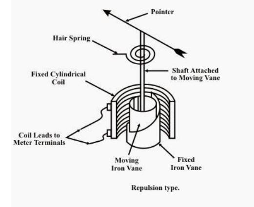
In repulsion type, a fixed vane or rod is also used and magnetized with the same
polarity. Control torque is provided
by spring or weight (gravity).
Damping torque is normally pneumatic, the
damping device consisting of an air chamber and a moving vane attached to the instrument spindle.
Deflecting torque produces
a movement on an aluminum pointer over a graduated scale.
The deflecting torque in any moving-iron
instrument is due to forces on a small piece of magnetically ŌĆśsoftŌĆÖ iron that is
magnetized by a coil carrying theoperating current. In repulsion type
movingŌĆōiron instrument consists of two cylindrical soft iron vanes mounted
within a fixed current-carrying coil. One iron vane is held fixed to the coil
frame and other is free to rotate, carrying with it the pointer shaft. Two
irons lie in the magnetic field produced by the coil that consists of only few
turns if the instrument is an ammeter or of many turns if the instrument is a
voltmeter.
Current
in the coil induces both vanes to become magnetized and repulsion between the
similarly magnetized vanes produces a proportional rotation. The deflecting
torque is proportional to the square of the current in the coil, making the
instrument reading is a true
ŌĆśRMSŌĆÖ
quantity Rotation is opposed by a hairspring that produces the restoring torque
. Only the fixed coil carries load current, and it is constructed so as to
withstand high transient current.
Moving
iron instruments having scales that are nonlinear and somewhat crowded in the
lower range of calibration.
Measurement of Electric Voltage and Current
Moving
iron instruments are used as Voltmeter and Ammeter only.
Both can
work on AC as well as on DC.
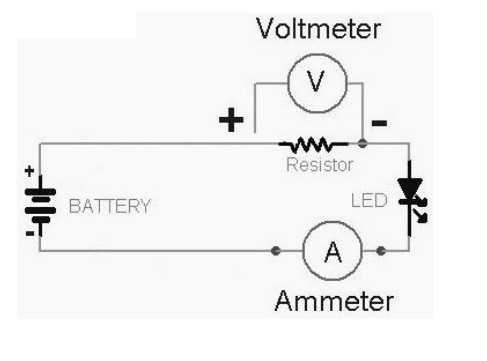
Ammeter
Instrument
used to measure current in the circuit.
Always
connected in series with the circuit and carries the current to be measured.
This current flowing through the coil produces the desired deflecting torque.
It should
have low resistance as it is to be connected in series.
Voltmeter
Instrument
used to measure voltage between two points in a circuit.
Always
connected in parallel.
Current
flowing through the operating coil of the meter produces deflecting torque.
It should
have high resistance. Thus a high resistance of order of kilo ohms is connected
in series with the coil of the instrument.
Ranges of Ammeter and Voltmeter
For a
given moving-iron instrument the ampere-turns necessary to produce full-scale
deflection are constant.
One can
alter the range of ammeters by providing a shunt coil with the moving coil.
Voltmeter
range may be altered connecting a resistance in series with the coil. Hence the
same coil winding specification may be employed for a number of ranges.
Advantages
1. The
instruments are suitable for use in AC and DC circuits.
2. The
instruments are robust, owing to the simple construction of the moving parts.
3. The
stationary parts of the instruments are also simple.
4. Instrument
is low cost compared to moving coil instrument.
5. Torque/weight
ratio is high, thus less frictional error.
Errors
(i).
Error due to variation in temperature.
(ii).
Error due to friction is quite small as torque-weight ratio is high in moving
coil instruments.
(iii).
Stray fields cause relatively low values of magnetizing force produced by the
coil. Efficient magnetic screening is essential to reduce this effect.
(iv).
Error due to variation of frequency causes change of reactance of the coil and
also changes the eddy currents induced in neighbouring metal.
(v).
Deflecting torque is not exactly proportional to the square of the current due
to non -linear characteristics of iron material.
Attraction type
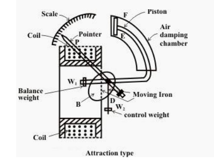
The basic
construction of attraction type moving iron instrument is illustrated bellow A
thin disc of soft iron is eccentrically pivoted in front of a coil. This iron
tends to move inward that is from weaker magnetic field to stronger magnetic
field whencurrent flowing through the coil. In attraction moving instrument
gravity control was used previously but now gravity control method is replaced
by spring control in relatively modern instrument. By adjusting balance weight
null deflection of the pointer is achieved. The required damping force is
provided in this instrument by air friction. The figure shows a typical type of
damping system provided in the instrument, where damping is achieved by a
moving piston in an air syringe.
Theory of Attraction Type Moving Iron Instrument
Suppose
when there is no current through the coil, the pointer is at zero, the angle
made by the axis of the iron disc with the line perpendicular to the field is
Žå. Now due current I and corresponding magnetic field strength, the iron piece
is deflected to an angle ╬Ė. Now component of H in the direction of defected
iron disc axis is Hcos{90 - (╬Ė + Žå) or Hsin(╬Ė + Žå). Now force F acting on the
disc inward to the coil is thus proportional to H2sin(╬Ė + Žå) hence
the force is also proportional to I2sin(╬Ė + Žå) for constant
permeability. If this force is acting on the disc at a distance l from the
pivot, then deflection torque,
Td = Fl
cos (╬Ė+╬”)
Thus Td =
I2 sin (╬Ė+╬”) cos (╬Ė+╬”)
Td = kI2
sin 2(╬Ė+╬”)
Where k
is constant.
Now, as
the instrument is gravity controlled, controlling torque will be
Tc = kŌĆÖ
sin ╬Ė
Where k
ŌĆśis constant
Related Topics