Chapter: Linear Integrated Ciruits : Characteristics of op-amp
Open loop-op-amp Configuration
Open loop-op-amp Configuration:
The term
open-loop indicates that no feedback in any form is fed to the input from the
output. When connected in open – loop, the op-amp functions as a very high gain
amplifier. There are three open – loop configurations of op-amp namely
1.
differential amplifier
2.
Inverting amplifier
3.
Non-inverting amplifier
The above
classification is made based on the number of inputs used and the terminal to
which the input is applied. The op-amp amplifies both ac and dc input signals.
Thus, the input signals can be either ac or dc voltage.
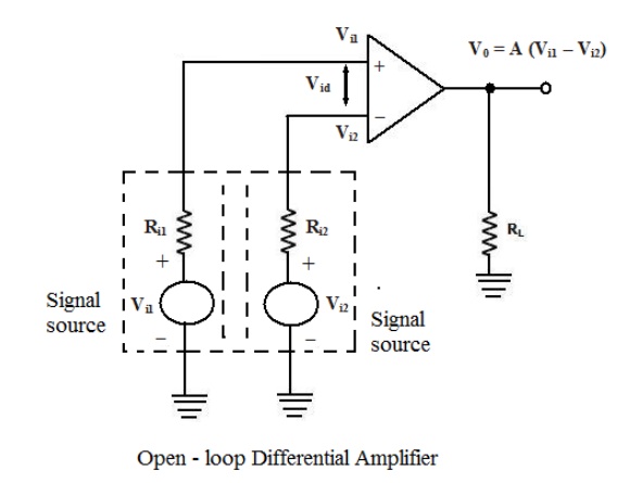
1. Open–loop Differential
Amplifier:
In this
configuration, the inputs are applied to both the inverting and the
non-inverting input terminals of the op-amp and it amplifies the difference
between the two input voltages. Figure shows the open-loop differential
amplifier configuration.
The input
voltages are represented by Vi1 and Vi2. The source
resistance Ri1 and Ri2 are negligibly small in comparison with the
very high input resistance offered by the op-amp, and thus the voltage drop
across these source resistances is assumed to be zero. The output voltage V0
is given by
V0
= A(Vi1 – Vi2 )
where A is the large signal voltage gain. Thus the output voltage is equal to the voltage gain A times the difference between the two input voltages. This is the reason why this configuration is called a differential amplifier. In open – loop configurations, the large signal voltage gain A is also called open-loop gain A.
2. Inverting amplifier:
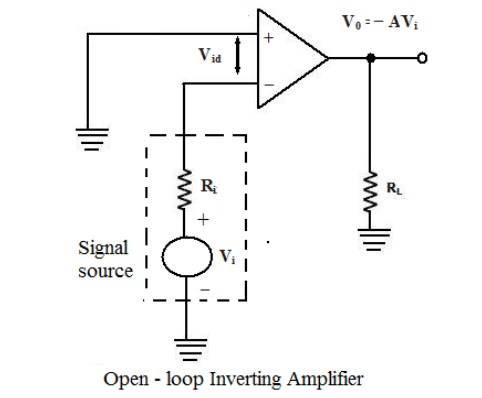
In this
configuration the input signal is applied to the inverting input terminal of
the op-amp and the non-inverting input terminal is connected to the ground.
Figure shows the circuit of an open – loop inverting amplifier.
The
output voltage is 1800 out of phase with respect to the input and
hence, the output voltage V0 is given by,
V0
= -AVi
Thus, in
an inverting amplifier, the input signal is amplified by the open-loop gain A
and in phase
– shifted
by 1800.
3. Non-inverting Amplifier
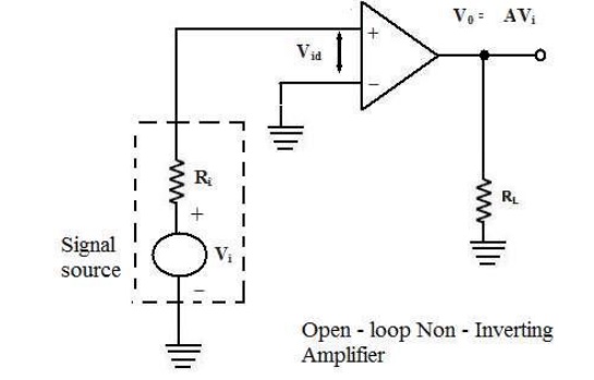
Figure
shows the open – loop non- inverting amplifier. The input signal is applied to
the non-inverting input terminal of the op-amp and the inverting input terminal
is connected to the ground.
The input
signal is amplified by the open – loop gain A and the output is in-phase with
input signal.
In all
the above open-loop configurations, only very small values of input voltages
can be applied. Even for voltages levels slightly greater than zero, the output
is driven into saturation, which is observed from the ideal transfer
characteristics of op-amp shown in figure. Thus, when operated in the open-loop
configuration, the output of the op-amp is either in negative or positive
saturation, or switches between positive and negative saturation levels. This
prevents the use of open – loop configuration of op-amps in linear
applications.
Limitations of Open – loop Op –
amp configuration:
Firstly,
in the open – loop configurations, clipping of the output waveform can occur
when the output voltage exceeds the saturation level of op-amp. This is due to
the very high open – loop gain of the op-amp. This feature actually makes it
possible to amplify very low frequency signal of the order of microvolt or even
less, and the amplification can be achieved accurately without any distortion.
However, signals of such magnitudes are susceptible to noise and the
amplification for those application is almost impossible to obtain in the
laboratory.
Secondly,
the open – loop gain of the op – amp is not a constant and it varies with
changing temperature and variations in power supply. Also, the bandwidth of most
of the open- loop op amps is negligibly small. This makes the open – loop
configuration of op-amp unsuitable for ac applications. The open – loop
bandwidth of the widely used 741 IC is approximately 5Hz. But in almost all ac
applications, the bandwidth requirement is much larger than this.
For the
reason stated, the open – loop op-amp is generally not used in linear
applications. However, the open – loop op amp configurations find use in
certain non – linear applications such as comparators, square wave generators
and astablemultivibrators.
Related Topics