Chapter: Design of Electrical Machines : Transformers
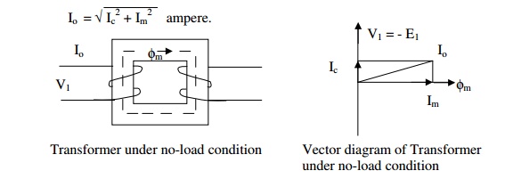
No-load current of a transformer
No-load current of a transformer
The phasor sum of the magnetizing
current (Im) and the loss component of current (I1) ; Im is calculated using
the MMF/m required for the core and yoke and their respective length of flux
path. I1 is determined using the iron loss curve of the material used for the
core and yoke and the flux density employed and their weight.
The no-load current I0 is
the vectorial sum of the magnetizing current Im and core loss or working
component current Ic. [Function of Im is to produce flux φm in the magnetic
circuit and the function of Ic is to satisfy the no load losses of the
transformer]. Thus,
No load input to the transformer = V1I0Cosφ0
= V1Ic = No load losses as the output is zero and input = output + losses.
Since the copper loss under no load
condition is almost negligible, the no load losses can entirely be taken as due to core loss only. Thus the core loss
component of the no load current
Ic = core loss / V1
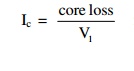
for single phase transformers
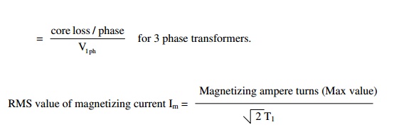
with the assumption that the
magnetizing current is sinusoidal (which is not true in practice)
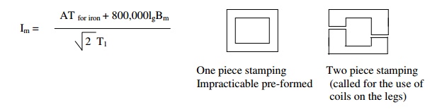
The magnetic circuit of a transformer consists
of both iron and air path. The iron path is due to legs and yokes and air path
is due to the unavoidable joints created by the core composed of different shaped
stampings. If all the joints are assumed to be equivalent to an air gap of lg
, then the total ampere turns for the transformer magnetic circuit is equal to
AT for iron + 800,000lgBm. Therefore,
Note:
1. In case of a transformer of
normal design, the no load current will generally be less than about 2% of the
full load current.
2. No load power factor Cosφ0
= Ic/I0 and will be around 0.2.
3. Transformer copper losses:
a) The primary copper loss at no
load is negligible as I0 is very less.
b) The secondary copper loss is zero
at no load, as no current flows in the secondary winding at no load.
4. Core or iron loss:
Total core loss = core loss in legs
+ core loss in yokes.
The core loss can be estimated at design
stage by referring to graph of core loss/kg versus flux density.
Core loss in leg = loss/kg in leg x
weight of leg in kg
= loss / kg in leg x volume of the leg (AiHw)
x density of steel or iron used
Core loss in yoke = loss/kg in Yoke
x volume of yoke (Ay x mean length of the yoke) x density of
iron used
The density of iron or steel used
for the transformer core lies between 7.55 to 7.8 grams/cc.
Related Topics