Chapter: Power System Operation and Control : Real Power Frequency Control
Model of Uncontrolled two Area Load Frequency Control System
MODEL OF UNCONTROLLED TWO AREA LOAD FREQUENCY CONTROL SYSTEM
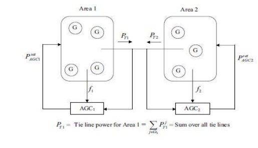
AGC IN A MULTI AREA SYSTEM
Ø In an interconnected (multi area) system, there will be one ALFC loop for each control area (located at the ECC of that area).
They are combined as shown in Fig for the interconnected system operation.
For a total change in load of ∆PD, the steady state Consider a two area system as depicted in Figure.
The two secondary frequency controllers, AGC1 and AGC2, will adjust the power reference values of the generators participating in the AGC.
In an N-area system, there are N controllers AGCi, one for each area i.
A block diagram of such a controller is given in Figure 4.2. A common way is to implement this as a proportional-integral (PI) controller:
Deviation in frequency in the two areas is given by
∆f=∆ω1=∆ω2=−∆PD / β1 + β2
where
β1 = D1 + 1/ R1
β2= D2+1/R2
E expression for tie-line flow in a two-area interconnected system Consider a change in load
∆PD1 in area1. The steady state frequency deviation ∆f is the same for both the areas.
That is ∆f =∆f1 =∆f2.
Thus, for area1, we have ∆Pm1 -∆PD1 -∆P12 = D1∆f
Where, Area 2 ∆P12 is the tie line power flow from Area1to Area 2; and for ∆Pm2 +∆P12 = D2∆f
The mechanical power depends on regulation.
Hence ∆Pm1= -∆f 1∆Pm2= -∆f 2 Substituting these equations, yields (1/R1+ D1) ∆f =-∆P12- ∆Pm
(1/R2+ D2) ∆f =-∆P12- ∆Pm
Solving for ∆f, we get
∆f= -∆PD1/ β1 + β2
Where β1 and β2 are the composite frequency response characteristic of Area1 and Area 2 respectively. An increase of load in area1 by ∆PD1 results in a frequency reduction in both areas and a tie-line flow of ∆P12. A positive ∆P12 is indicative of flow from Area1 to Area
2 while a negative ∆P12 means flow from Area 2 to Area1. Similarly, for a change in Area 2 load by ∆PD2, we have
∆f= -∆PD2/ β1 + β2
Related Topics