Chapter: Mechanical : Manufacturing Technology : Shaper, Milling and Gear Cutting Machines
Milling
Milling
Milling is a process of producing
flat and complex shapes with the use of multi-tooth cutting tool, which is
called a milling cutter and the cutting edges are called teeth. The axis of
rotation of the cutting tool is perpendicular to the direction of feed, either
parallel or perpendicular to the machined surface. The machine tool that traditionally
performs this operation is a milling machine. Milling is an interrupted cutting
operation: the teeth of the milling cutter enter and exit the work during each
revolution. This interrupted cutting action subjects the teeth to a cycle of
impact force and thermal shock on every rotation. The tool material and cutter
geometry must be designed to withstand these conditions. Cutting fluids are
essential for most milling operations. Three types of feed in milling can be
identified:
Feed per
tooth: the basic parameter in milling equivalent to the feed in turning.
Feed per tooth is selected with
regard to the surface finish and dim ensional accuracy required. Feeds per
tooth are i n the range of 0.05~0.5 mm/tooth, lower feeds are for finishing
cuts; feed per revolution: it
determines the amount of material cut per on e full revolution of the
milling cutter. Feed per revolution is calculated as fr = fz being the nu mber
of the cutter’s
teeth;
Feed per minute fm: Feed per minute is calculated taking into
account the rotational speed
N and
number of the cutter’s teeth z, fm = fzN = frN
Feed per minute is used to adjust the feed change gears.
Three types of feed in milling can be identified:
Feed per tooth fz: the basic pa rameter in milling equivalent
to the feed in t urning.
Feed per tooth is selected wit h
regard to the surface finish and dimensiona l accuracy required (see Section
5.10 Selection of Cutting Conditions). Feeds per tooth ar e in the range of
0.05~0.5 mm/tooth, lower feeds are for finishing cuts; feed per revoluti on fr:
it determines the amount of material cut pe r one full revolution of the
milling cutter. Fee d per revolution is calculated as
fr = fz ,z being the number of the cutter’s
teeth;
Feed per minute fm: Feed per
minute is calculated taking into account the rotational speed N and number of
the cutter’s tee th z, fm = fzN = fr,NFeed per minute is use d to
adjust the feed change gears. In down millin g, the cutting force is directed
into the work table, which allows thinner workparts tobe machined. Better
surface finish is obtained but the stress load on the teeth is abrupt, which
may da mage the cutter.In up milling, the cutting fo rce tend to lift the
workpiece. The work conditi ons for the cutter are more favourable. Because the
cutter does not start to cut when it makes contact (cutting at zero cut is
impossible), the surface has a natural waviness.
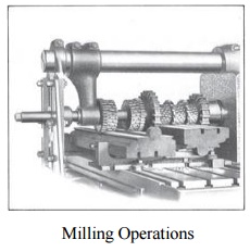
Milling Operations
Owing to the variety of shapes
possible and its high production rates, m illing is one of the most versatile
and widely used machining operations. The geometric form created by milling
fall into three major groups: P lane surfaces: the surface is linear in all thre
e dimensions. The simplest and most convenient type of surface;
Two-dimensional
surfaces: th e shape of the surface changes in the direc tion of two of the
axes and is linear along the third axis. Examples include cams;
Three-dimensional surfaces: the shape of the surface changes
in all three d irections.
Examples include die cavities, gas turbine blades, propellers,
casting patter ns, etc.
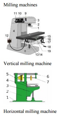
Milling
machines
Vertical
milling machine and
The conventional milling ma
chines provide a primary rotating motion fo r the cutter held in the spindle,
and a linear feed motion for the workpiece, which is fastened onto the
worktable. Milling machines for machin ing of complex shapes usually provide both
a rotating primary motion and a curvilinear fe ed motion for the cutter in the
spindle with a stationary workpiece. Various machine designs are available for
various milling operations. In this section we discuss only the most popular
ones, classified into the followin g types:
Column-and-knee milling ma chines; v Bed type milling
machines;
Machining
centers.
Column-and-knee milling ma chines
The column-and-knee millin g
machines are the basic machine tool for milling. The name comes from the fact
that this machine has two principal components, a column that supports the
spindle, and a knee that su pports the work table. There are two differen t
types of column-and-knee milling machines according to position of the spindle
axis:
horizontal, and vertical.
Milling cutters
Brazed cutters: Very limited
numbers of cutters (mainly face mills) are made with brazed carbide inserts.
This design is largely replaced by mechanically attached cuutters.
Mechanically
attached cutters: The vast majority of cutters are in this category. Carbide
inserts are either clamped or p in locked to the body of the milling cutter.
Classification of milling cutters may also be associated with
the various milling operations
Related Topics