Chapter: Electrical machines : Single Phase Induction Motor and Special Machines
Methods of Starting Single Phase Induction Motor
Methods of Starting
It is clear from previous discussion that a single phase induction motor when having only one winding and it is not self-starting. To make it a self-starting anyone of the following can be adopted.
(1) Split phase starting.
(2) Repulsion starting.
(3) Shaded pole starting.
PRINCIPLE OF SPLIT PHASE INDUCTION MOTOR
The basic principle of operation of a split phase induction motor is similar to that of a polyphaseinduction motor. The main difference is that the single phase motor does not produce a rotating magnetic field but produces only a pulsating filed.
Hence, to produce the rotating magnetic field for self-starting, phase splitting is to be done to make the motor to work as a two phase motor for starting.
Working of Split Phase Motor
In split phase motor two windings named as main winding and starting winding are provided. At the time of starting, both the main and starting windings should be connected across the supply to produce the rotating magnetic field.
The rotor is of a squirrel cage type and the revolving magnetic field sweeps part the stationary rotor, inducing emf in the rotor. As the rotor bars are short-circuited, a current flows through them producing a magnetic field.
This magnetic field opposes the revolving magnetic field and will combine with the main filed to produce a revolving filed. By this action, the rotor starts revolving in the same direction of the rotating magnetic field as in the case of a squirrel cage induction motor.
Hence, once the rotor starts rotating, the starting winding can be disconnected from the supply by some mechanical means as the rotor and stator fields from a revolving magnetic field. There are several types of split phase motors.
TYPES OF SPLIT-PHASE INDUCTION MOTORS
1. Resistance-start, induction-run motors
2. Capacitor-start, induction-run motors
3. Capacitor-start, capacitor-run motors
4. Shaded pole motors.
1. RESISTANCE-START, INDUCTION-RUN MOTORS
As the starting torque of this type of motor is relatively small and its starting current is high, these motors are most commonly used for rating up to 0.5 HP where the load could be started easily. The essential parts are shown in Fig:
Main winding or running winding.
Auxiliary winding or starting winding
Squirrel cage type rotor.
Centrifugal switch.
CONSTRUCTION AND WORKING
The starting winding is designed to have a higher resistance and lower reactance than the main winding. This is achieved by using small conductors in the auxiliary winding than in the main winding. The main winding will have higher inductance when surrounded by more iron, which could be made possible by placing it deeper into the stator slots, it is obvious that the current would split as shown in Fig: (b).
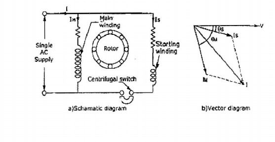
The starting current "I" start will lag the main supply voltage "V" line by 15 degree and the main winding current. "I" main lags the main voltage by about 80 degree. Therefore, these currents will differ in time phase and their magnetic fields will combine to produce a rotating magnetic field.
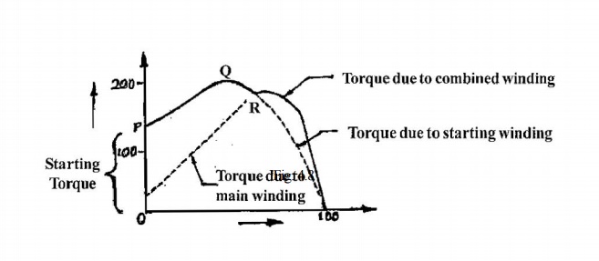
When the motor has comeupto about 75 to 80% of synchronous speed, the starting winding is opened by a centrifugal switch and the motor will continue to operate as a single phase motor.
CHARACTERISTICS
At the point where the starting winding is disconnected, the motor develops nearly as much torque with the main winding alone as with both windings connected. This can be observed from, the typical torque-speed characteristics of this motor, as shown in Fig:.
The direction of rotating of a split-phase motor is determined by the way the main and auxiliary windings are connected. Hence, either by changing the main winding terminals or by changing the starting winding terminals, the reversal of direction of rotating could be obtained.
APPLICATIONS
These motors are used for driving fans, grinders, washing machines.
2. CAPACITOR-START, INDUCTION-RUN MOTOR
A drive which requires a large starting torque may be fitted with a capacitor-start, induction-run motor as it has excellence starting torque as compared to the resistance-start, induction-run motor.
CONSTRUCTION AND WORKING
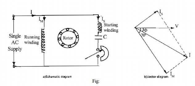
Fig: (a) shows the schematic diagram of a capacitor-start, induction-run motor. As shown, the main winding is directly connected across the main supply whereas the starting winding is connected across the main supply through a capacitor and centrifugal switch.
Both these windings are placed in a stator slot at 90 degree electrical apart, and a squirrel cage type rotor is used.
As shown in Fig: (b), at the time of starting the current in the main winding lags the supply voltages by 90 degrees, depending upon its inductance and resistance. On the other hand, the current in the starting winding due to its capacitor will lead the applied voltage, by say 20 degrees.
Hence, the phase difference between the main and starting winding becomes near to 90 degrees. This in turn makes the line current to be more or less in phase with its applied voltage, making the power factor to be high, thereby creating an excellent starting torque.
However, after attaining 75% of the rated speed, the centrifugal switch operates opening the starting winding and the motor then operates as an induction motor, with only the main winding connected to the supply.
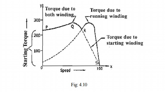
As shown in Fig: 4.9(b), the displacement of current in the main and starting winding is about 80/90 degrees, and the power factor angle between the applied voltage and line current is very small. This results in producing a high power factor and an excellent starting torque, several times higher than the normal running torque as shown in Fig:
CHARACTERISTICS
The torque-speed characteristics of this motor is shown in Fig:.
In order to reverse the direction of rotation of the capacitor-start, induction-run motor, either the starting or the main winding terminals should be changed.
This is due to the fact that the direction of rotation depends upon the instantaneous polarities of the main field flux and the flux produced by the starting winding. Therefore, reversing the polarity of one of the field will reverse the torque.
APPLICATIONS
Due to the excellent starting torque and easy direction-reversal characteristics,
Used in belted fans,
Used in blowers dryers,
Used in washing machines,
Used in pumps and compressors.
3. CAPACITOR-START, CAPACITOR-RUN MOTORS
As discussed earlier, one capacitor-start, induction-run motors have excellent starting torque, say about 300% of the full load torque and their power factor during starting in high.
However, their running torque is not good, and their power factor, while running is low. They also have lesser efficiency and cannot take overloads.
CONSTRUCTION AND WORKING
The aforementioned problems are eliminated by the use of a two valve capacitor motor in which one large capacitor of electrolytic (short duty) type is used for starting whereas a smaller capacitor of oil filled (continuous duty) type is used for running, by connecting them with the starting winding as shown in Fig:. A general view of such a two valve capacitor motor is shown in Fig:.
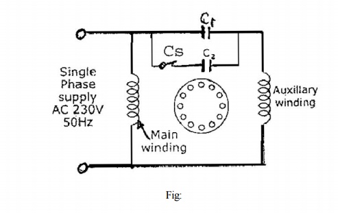
This motor also works in the same way as a capacitor-start, induction-run motor, with exception, that the capacitor C1 is always in the circuit, altering the running performance to a great extent.
The starting capacitor which is of short duty rating will be disconnected from the starting winding with the help of a centrifugal switch, when the starting speed attains about 75% of the rated speed.
CHARACTERISTICS
The torque-speed characteristics of this motor is shown in Fig:.
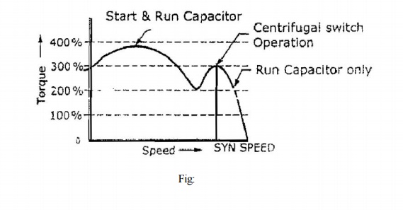
This motor has the following advantages:
• The starting torque is 300% of the full load torque
• The starting current is low, say 2 to 3 times of the running current.
• Starting and running power factor are good.
• Highly efficient running.
• Extremely noiseless operation.
• Can be loaded upto 125% of the full load capacity.
APPLICATIONS
• Used for compressors, refrigerators, air-conditioners, etc.
• Higher starting torque.
• High efficiency, higher power factor and overloading.
• Costlier than the capacitor-start — Induction run motors of the same capacity.
REPULSION STARTING
This type of starting need a wound rotor with brush and commutator arrangement like a dc armature Fig 4.13(a). The starting operation is based on the principle of repulsion and hence the name.
CONSTRUCTION AND WORKING
Repulsion starting, though complicated in construction and higher in cost, are still used in certain industries due to their excellent starting torque, low starting current, ability to withstand long spell of starting currents to drive heavy loads and their easy method of reversal of direction.
Now there is a condition that the rotor north pole will be repelled by the main north pole and the rotor south pole is repelled by the main south pole, so that a torque could be developed in the rotor. Now due to the repulsion action between the stator and the rotor poles, the rotor will start rotating in a clockwise direction. As the motor torque is due to repulsion action, this starting method is named as repulsion starting.
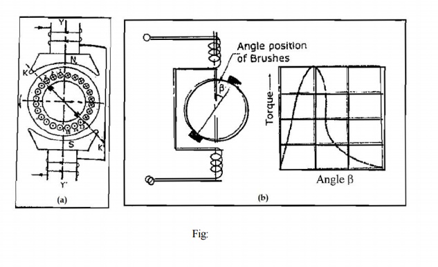
To change the direction of rotation of this motor, the brush axis needs to be shifted from the right side as shown in Fig: (b) to the left side of the main axis in a counter clockwise direction as shown in Fig: (b).
CHARACTERISTICS
The torque developed in a repulsion motor will depend upon the amount of brush shaft as shown in Fig: 4.13 (b), whereas the direction of shift decides the direction of rotation.
Further, the speed depends upon the amount of brush shift and the magnitude of the load also on the relationship between the torque and brush-position angle.
Though the starting torque from 250 to 400% of the full load torque, the speed will be dangerously high during light loads. This is due to the fact that the speed of the repulsion motor start does not depend on frequency or number of poles but depends upon the repulsion principle.
Further, there is a tendency of sparking in the brushes at heavy loads, and the PF will be poor at low speeds. Hence the conventional repulsion motor start is not much popular.
SHAPED POLE STARTING
The motor consists of a yoke to which salient poles are fitted as shown in Fig: 4.14(a) and it has a squirrel cage type rotor.
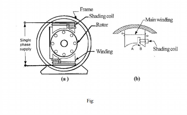
A shaded pole made of laminated sheets has a slot cut across the lamination at about one third the distance from the edge of the pole.
Around the smaller portion of the pole, a short-circuited copper ring is placed which is called the shading coil, and this part of the pole is known as the shaded part of the pole. The remaining part of the pole is called the unshaded part which is clearly shown in Fig: (b).
Around the poles, exciting coils are placed to which an AC supply is connected. When AC supply is effected to the exciting coil, the magnetic axis shifts from the unshaded part of the pole to the shaded part as will be explained in details in the next paragraph. This shifting of axis is equivalent to the physical movement of the pole.
This magnetic axis, which is moving, cuts the rotor conductors and hence, a rotational torque is developed in the rotor.
By this torque the rotor starts rotating in the direction of the shifting of the magnetic axis that is from the unshaded part to the shaded part.
THE MAGNETIC FLUX SHIFTING
As the shaded coil is of thick copper, it will have very low resistance but as it is embedded in the iron case, it will have high inductance. When the exciting winding is connected to an AC supply, a sine wave current passes through it.
Let us consider the positive half cycle of the AC current as shown in Fig:
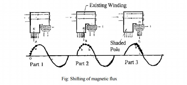
When the current raises from "Zero" Value of point "0" to a point "a" the change in current is very rapid (Fast). Hence, it reduces an emf in the shaded coil on the basis of Faraday's law of electromagnetic induction.
The induced emf in the shaded coil produces a current which, in turn, produces a flux in accordance with Lenz Law. This induced flux opposes the main flux in the shaded portion and reduces the main flux in that area to a minimum value as shown in Fig:.
This makes the magnetic axis to be in the centre of the unshaded portion as shown by the arrow in part of Fig:. On the other hand as shown in part 2 of 3 when the current raises from point "a" to point "b" the change in current is slow the induced emf and resulting current in the shading coil is minimum and the main flux is able to pass through the shade portion.
This makes the magnetic axis to be shifted to the centre of the whole pole as shown in by the arrow in part 2 of Fig:
In the next instant, as shown in part 3 of Fig:. When the current falls from "b" to "c" the change in current is fast but the change of current is from maximum to minimum.
Hence a large current is induced in the shading ring which opposes the diminishing main flux, thereby increasing the flux density in the area of the shaded part. This makes the magnetic axis to shift to the right portion of the shaded part as shown by the arrow in part.
From the above explanation it is clear the magnetic axis shifts from the unshaded part to the shaded part which is more or less a physical rotary movement of the poles.
Simple motors of this type cannot be reversed. Specially designed shaded pole motors have been constructed for reversing operations. Two such types:
a. The double set of shading coils method
b. The double set of exciting winding method.
Shaded pole motors are built commercially in very small sizes, varying approximately from 1/250 HP to 1/6 HP. Although such motors are simple in construction and cheap, there are certain disadvantages with these motor as stated below:
• Low starting torque.
• Very little overload capacity.
• Low efficiency.
APPLICATIONS
• Record players
• Fans
• Hair driers.
Related Topics