Chapter: Civil : Railway Airport Harbour Engineering : Railway Engineering : Railway Tunnelling
Methods of Railway Tunnelling
Methods of Tunnelling
There are various methods of
tunnelling. The selection of a method depends upon the size of the bore, the
condition of the ground, the equipment available, and the extent to which
timbering is required. Tunnelling may be basically divided into two main
groups.
(a) Tunnelling
in hard rocks
(b) Tunnelling
in soft rocks
These are described in detail in
the subsequent sections. Tunnelling through water-bearing strata and compressed
air tunnelling are discussed subsequently.
1 Tunnelling in Hard Rocks
The following methods are generally employed for tunnelling in
hard rocks.
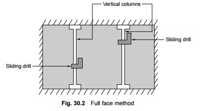
Full face method
The full face method is normally
selected for small tunnels whose dimensions do not exceed 3 m. In this method,
the full face or the entire facade of the tunnel is tackled at the same time.
Vertical columns are erected at the face of the tunnel and a large number of
drills mounted or fixed on these columns at a suitable height as shown in Fig.
3.2. A series of holes measuring 10 mm to 40 mm in diameter with about 1200 mm
centre-to-centre distance are then drilled into the rock, preferably in two
rows. These holes are charged with explosives and ignited. Next the muck is
removed before repeating the process of drilling holes.
Advantages
(a) Since an
entire section of the tunnel is tackled at one time, the method is completed
expeditiously.
(b) Mucking
tracks, which are tracks used for collecting muck, can be laid on the tunnel
floor and extended as the work progresses.
(c) With the
development of the 'jumbo' or drill carriage, this method can be used for
larger tunnels too.
Disadvantages
(a) The
method requires heavy mechanical equipment.
(b) It is not
very suitable for unstable rocks.
(c) It can
normally be adopted for small tunnels only.
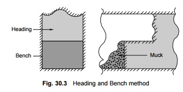
Heading and bench method
In this method, the heading (top
or upper half) of the tunnel is bored first and then the bench (bottom or lower
half) follows. The heading portion lies about 3.70 m to 4.60 m ahead of the
bench portion (Fig. 30.3). In hard rock, the drill holes for the bench are
driven at the same time as the removal of the muck. The hard rock permits the
roof to stay in place without supports.
Advantages
(a) The work
of drilling of holes for the explosives and the removal of muck can progress
simultaneously.
(b) This
method requires the use of lower quantities of gunpowder than the full face
method.
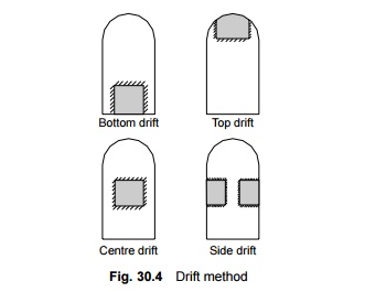
Drift method
A drift is a small tunnel
measuring 3 m � 3 m, which is driven into the rock and whose section is widened
in subsequent processes till it equates that of the tunnel. A number of drill
holes are provided all around the drift and these are filled up with explosives
and ignited so that the size of the drift expands to become equal to the
required cross section of the tunnel.
The position of the drift depends
upon local conditions; it may be in the centre, top, bottom, or side as shown
in Fig. 30.4. Field experience has shown that the central drift is the best
choice, as it offers better ventilation and requires lower quantities of
explosives. The side drift, however, has the advantage that it permits the use
of timber to support the roof.
Advantages
(a) If the
quality of the rock is bad or if it contains excessive water, this is detected
in advance and corrective measures can then be taken in time.
(b) A drift
assists in the ventilation of tunnels.
(c) The
quantity of explosives required is less.
(d) A side
drift allows the use of timber to support the roof.
Disadvantages
(a) It is a
time-consuming process, as the excavation of the main tunnel gets delayed till
the drift is completed.
(b) The cost
of drilling and removing the muck from the drift is high, as the work has to be
done using manually operated power-driven equipment.
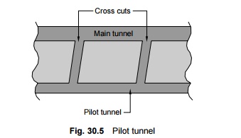
Pilot tunnel method
This method normally involves the
digging of two tunnels, namely, a pilot tunnel and a main tunnel. The cross
section of the pilot tunnel usually measures about 2.4 m � 2.4 m. The pilot
tunnel is driven parallel to the main tunnel and connected to the centre line
of the main tunnel with cross cuts at many points. The main tunnel is then
excavated from a number of points. The pilot tunnel offers the following
advantages.
(a) It helps
in removing the muck from the main tunnel quickly.
(b) It helps
in providing proper ventilation and lighting in the main tunnel. The method,
however, requires the construction of an additional tunnel and therefore the
time and cost of construction are higher as compared to the methods described
before.
Perimeter method of tunnelling
In this method, the excavation is
carried out along the perimeter or periphery of the section. The method is also
known as the German method.
2 Tunnelling in Soft Ground or Soft Rock
Tunnelling in soft ground or soft
rock is a specialized job. It does not involve the use of explosives and the
requisite excavation work is done using hard tools such as pickaxes and
shovels. In recent times, compressed air has also been used for this purpose.
During excavation, the rail requires support at the sidewalls and the roofs
depending upon the type of soil. The support could be provided in the form of
timber or steel plates or other similar material. The various operations
involved in soft rock tunnelling are as follows.
(a) Excavation
or mining
(b) Removal
of excavated material
(c) Scaffolding
and shuttering
(d) Lining of
tunnel surface
The nature of the ground is the
most important factor in deciding the method to be used for tunnelling. The
types of ground which are generally encountered in the field are detailed in
Table 30.3.
Table 30.3 Types of grounds
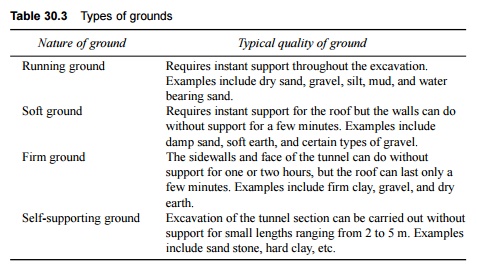
In the case of soft rock, the
selection of the method of tunnelling depends upon the following important
factors.
(a) Nature of
ground
(b) Size of
tunnel
(c) Equipment
available
(d) Sequence
of operations
Some of the important methods of
tunnelling in soft rock are described in the following sections.
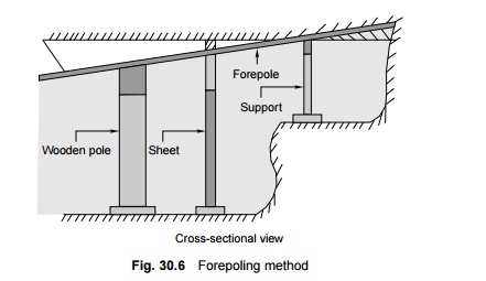
Forepoling method
Forepoling is an old method of
tunnelling through soft ground. In this method, a frame is prepared in the
shape of the letter A, placed near the face of the tunnel, and covered with
suitable planks. Poles are then inserted at the top of the frame up to a viable
depth. The excavation is carried out below these poles, which are supported by
vertical posts. The excavation is carried out on the sides and the excavated
portion is suitably supported by timber. The entire section of the tunnel is
covered thus. The process is repeated as the work progresses.
Forepoling is a slow and tedious
process and requires skilled manpower and strict supervision. The method has to
be meticulously repeated in sequence and there is no short cut for the same.
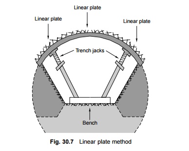
Linear plate method
In the linear plate method (Fig.
30.7), timber is replaced by standard size pressed steel plates. The use of
pressed steel plates is a recent development. The method has the following
advantages.
(a) The
linear plates are light and can be handled easily.
(b) The
number of joints is less, as the linear plates are bigger in size, and as
such the
maintenance cost is low.
(a) The steel
plates are fireproof and can be safely used while working in compressed air
condition.
(d) The
necessary work can be done by semi-skilled staff.
(e) There is
considerable saving in terms of the excavation and concrete required.
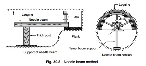
Needle beam method
The needle beam method (Fig.
30.8) is adopted in terrains where the soil permits the roof of the tunnel
section to stand without support for a few minutes. In this method, a small
drift is prepared for inserting a needle beam consisting of two rail steel (RS)
joists or I sections and is bolted together with a wooden block in the centre.
The roof is supported on laggings carried on the wooden beam. The needle beam
is placed horizontally with its front end supported on the drift and the rear
end supported on a vertical post resting on the lining of the tunnel. Jacks are
fixed on the needle beam and the tunnel section is excavated by suitably
incorporating timber. This method of tunnelling is more economical compared to
other methods.
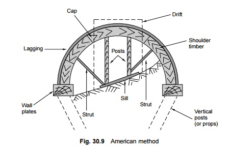
American method
In this method (Fig. 30.9), a
drift is driven into the top of the tunnel. The drift is supported by laggings,
caps, and two vertical posts. The sides of the drift are then widened and
additional support is provided using timber planks and struts. The process of
widening is continued till it reaches the springing level. Wall plates are
fixed at the springing level, which in turn are supported by vertical posts.
The vertical posts now occupy the entire roof level. The posts supporting the
drift can then be removed and tunnelling work continued further in a similar
manner.
English method
This method is similar to the
American method except that the roof load is supported by underpinning instead
of using vertical posts. A drift is driven into the top of the tunnel about 5 m
ahead of the existing arch lining. The drift is subsequently widened on both
sides and supported by crown bars and posts. The work is carried on till the
springing level is reached. The sill is then extended across the tunnel and the
extended piece is supported by underpinning. This method requires good quality
timber as well as simultaneous and frequent shifting from place to place.
Austrian method
This method is used for long
tunnels, particularly those at great depths, where the walls of the excavation
may yield under the weight of the cover. It involves excavating the whole
section for a short length and furnishing with sidewalls and an arch.
Belgian method
This method is particularly
suitable for areas where the height of the overburden is less and the surface
is not to be disturbed. In this case, the heading is excavated first and
supported by crown bar posts and laggings. The sides are excavated next and
supported by crown bars and posts. Finally, the work of lining the arch is
carried out and further excavation is done.
3 Tunnelling Through Water-bearing Strata
Tunnelling through subaqueous or
water-bearing strata is quite a different job. Shield tunnelling is generally
preferred in such cases. A shield is a movable frame that is used to support
the face of a tunnel. The tunnel is excavated and lined under the protection of
the shield.
A shield is a device meant for
excavation that is to be carried out beneath water-bearing strata. It basically
consists of a cutting edge, a skin plate in the form of a shell structure, and
a hood of jacks, ring girders, stiffening steel plates, ports as well as port
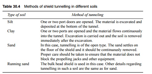
doors, and a tail. The various methods of shield tunnelling through different
types of soils are enumerated in Table 30.4.
Table 30.4 Methods of shield
tunnelling in different soils
Tunnels constructed using the
shield method usually have a circular section because of the following
considerations.
(a) The
rotation of the shield is easy in a circular section.
(b) It grants
protection to the primary lining.
(c) The
circular section provides the maximum cross-sectional area with the smallest
perimeter.
(d) The
circular section is ideally suited to resist the semi-fluid pressure exerted by
the soft ground.
4 Compressed Air Tunnelling
This method is possibly the most
modern method of tunnelling. The compressed air, which has a pressure of about
1 kg/cm2, is forced into the enclosed space within the tunnel so
that the sides and top of the tunnel do not collapse and remain in their position.
The equipment for tunnelling consists of a bulk head, which is an airtight
diaphragm with an airlock. The airlock is an airtight cylindrical steel chamber
with a door at each end opening inwards.
Tunnelling by means of compressed
air is quite a difficult process because of the following reasons.
(a) The
pressure inside the earth varies from the bottom to the top of the tunnel.
(b) It is not
possible to ascertain the pressure on the floor of the tunnel as it depends
upon the nature of the strata.
(c) The
pressure varies from strata to strata depending upon the moisture content,
which is difficult to ascertain.
(d) The compressed air normally escapes through the pores and the air pressure diminishes continuously. The application of air pressure has to be varied from time to time in order to achieve a balanced value. The determination of this value depends more on experience than on technical considerations.
Related Topics