Chapter: Mechanical : Metrology and Measurements : Measurement of Power, Flow and Temperature Related Properties
Measurement of Force
MEASUREMENT OF FORCE
The mechanical quantity which changes or
tends to change the motion or shape of a body to which it is applied is called
force. Force is a basic engineering parameter, the measurement of which can be
done in many ways as follows:
·
Direct methods
·
Indirect methods
·
Direct methods
It involves a direct comparison with a
known gravitational force on a standard mass, say by a balance.
· Indirect methods
It involves the measurement of effect of
force on a body, such as acceleration of a body of known mass subjected to
force.
Devices to measure
Force
·
Scale and balances
a. Equal
arm balance
b. Unequal
arm balance
c. Pendulum
scale
·
Elastic force meter (Proving ring)
·
Load cells
a. Strain
gauge load cell
b. Hydraulic
load cell
c.
Pneumatic load cell
Scale and balances
a.
Equal arm balance
An equal arm balance works on the
principle of moment comparison. The beam of the equal arm balance is in
equilibrium position when,
Clockwise rotating moment =
Anti-clockwise rotating moment M2L2 = M1L1
That
is, the unknown force is balanced against the known gravitational force.
Description
The
main parts of the arrangement are a follows:
·
A beam whose centre is pivoted and rests
on the fulcrum of a knife edge. Either side of the beam is equal in length with
respect to the fulcrum
·
A pointer is attached to the center of
the beam. This pointer will point vertically downwards when the beam is in
equilibrium.
·
A Provision to place masses at either
end of the beam.
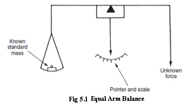
Operation
• A
known standard mass (m1) is placed at one end of the beam and an unknown mass
(m2) is placed at its other end.
• Equilibrium condition exists when, clockwise rotating moment = Anti-
clockwise rotating moment
·
Moreover at a given location, the ear
masses (m1 and m2) and hence at equilibrium condition. W1=W2. That is, the
unknown force (weight) will be equal to the known
force (weight).
b. Unequal
arm balance
An
unequal arm balance works on the principle of moment comparison.
The
beam of the unequal arm balance is in equilibrium position when,
Clockwise
rotating moment = Anti-clockwise rotating moment
F
x L2 = Fx x L1
Description
The
main parts of the arrangements are as follows:
·
A
graduated beam pivoted
to a knife
ed
·
A leveling pointer is attached to the
beam
·
A known mass “m” is attached to the r
unknown forcem”“F”can. Thisslidemasson the“ right
·
Provisions are made tox”
applyontheanleftunknos beam.
Operation
·
An unknown force “Fx” is applied on t
edge “Z” as shown
·
Now the positi”on theof
massright“mside of th the leveling pointer reads null balance position. When
the leveling pointer is
in null balance position, the beam is in
equilibrium.
Clock wise rotating moment = Anti-clock wise
rotating moment
Fx.L1
= F. L2
Fx
= Mg.L2/L1
·
Thus the unknownx”is
proportionalforce“F2”oftothethemad “m” from the knife edge “Y”
·
The right hand side of the beam which is
graduated is calibrated to get a direct
measurex” of
“F
c.
Pendulum Scale(Multi-lever Type)
It is a moment comparison device. The
unknown force is converted to torque which is then balanced by the torque of a
fixed standard mass arranged as a pendulum.
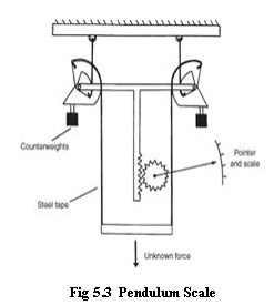
Description
• The
scale’s frames carry
support ribb These support ribbons
are attached to the sectors. The loading ribbons are attached to the sectors
and the load rod a shown. The load rod is inturn attached to the weighing
platform.
• The two sectors are connected on either side of an
equalizer beam. The sectors carry counter weighs. To the center of the equalizer beam is attached a rack and
pinion arrangement.
• A
pointer is attached
to the pinion
which sweeps over
a weight (force)
calibrated scale.
Operation
·
The unknown force is applied to the load
rod. Due to this force, the loading tapes are pulled downwards. Hence the
loading tapes rotate the sectors.
·
As the sectors rotate about the pivots,
it moves the counter weights outwards, This movements increases the counter
weight effective moment until the torque produced by the force applied to the
load rod and the moment produced by the counter weight balance each other,
thereby establishing an equilibrium.
·
During the process of establishing
equilibrium, the equalizer beam would be displaced downwards. As the rack is
attached to the equalizer beam, the rack also is displaced downwards rotating
the pinion.
·
As the pointer is attached to the
pinion, the rotation of the pinion makes the pointer to assume a new position
on the scale. The scale is calibrated to read the weight directly. Thus the
force applied on the load rod is measured.
Elastic force meter (Proving
Ring)
When a steel ring is subjected to a force across its
diameter, it deflects. This deflection is proportional to the applied force
when calibrated.
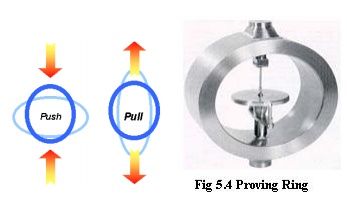
Description
A steel ring attached with external bosses to apply
force. A precision micrometer with one of its ends mounted on a vibrating reed.
Operation
·
The force to be measured is applied to
the external bosses of the proving ring. Due to the applied force, the ring
changes in diameter. This deflection of the ring is proportional to the applied
force.
·
At this stage, the reed is plucked to
obtain a vibrating motion. When the reed is vibrating, the micrometer wheel is
turned until the micrometer contact moves forward and makes a noticeable
damping of the vibrating reed.
·
Now the micrometer reading is noted
which is a measure of deflection of the ring. The device is calibrated to get a
measure of force in terms of deflection of the proving ring.
Load cells
a.
Strain gauge load cell
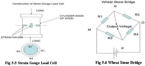
·
When a steel cylinder is subjected to a
force, it tends to change in dimension. On this cylinder if strain gauges are
bonded, the strain gauge also is stretched or compressed, causing a change in
its length and diameter.
·
This change in dimension of the strain
gauge causes its resistance to change.
This change
in resistance of the strain
gauge becomes a
measure of the
applied
force.
Description
· A cylinder made of
steel on which four identical strain gauges are mounted.
·
Out of the four strain gauges, two of
them (R1 and R4) are mounted along the direction of the applied load(Vertical
gauges)
·
The other tow strain gauges (R2 and R3
horizontal gauges) are mounted circumferentially at right angles to gauges R1
and R4.
·
The four gauges are connected to the
four limbs of wheat stone bridge. Operation
·
When there is no load on the steel
cylinder, all the four gauges will have the same resistance. As the terminals N
and P are at the same potential, the wheat stone bridge is balanced and hence
the output voltage will be zero.
·
Now the force to be measured is applied
on the steel cylinder. Due to this, the vertical gauges R1 and R4 will under go
compression and hence there will be a decrease in resistance. At the same time,
the horizontal gauges R2 and R3 will undergo tension and there will be an
increase in resistance. Thus when strained, the resistance of the various
gauges change.
·
Now the terminals N and P will be at
different potential and the change in output voltage due to the applied load
becomes a measure of the applied load when calibrated.
b. Hydraulic
Load Cell
·
When a force is applied on liquid medium
contained in a confined space, the pressure of the liquid increases. This
increase in pressure of the liquid is proportional to the applied force. Hence
a measure of the increase in pressure of the liquid becomes a measure of the
applied force when calibrated.
• The
force to be measure is applied to the piston
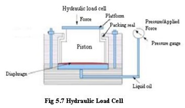
• The
applied force moves the piston down wards and deflects the diaphragm and this
deflection of the diaphragm increase the pressure in the liquid medium.
• This
increase in pressure of the liquid medium is proportional to the applied force.
This increase in pressure is measured by the pressure gauge which is connected
to the liquid medium.
• The
pressure is calibrated in force units and hence the indication in the pressure
gauge becomes a measure of the force applied on the piston.
b. Pneumatic
load cells
• If a
force is applied to one side of a diaphragm and an air pressure is applied to
the other side, some particular value of pressure will be necessary to exactly
balance the force. This pressure is proportional to the applied force.
• The
force to be measured is applied to the top side of the diaphragm. Due to
this force, the diaphragm deflects and
causes the flapper to shut-off the nozzle opening.
• Air
supply is provided at the bottom of the diaphragm. As the flapper closes the
nozzle opening, a back pressure results underneath the diaphragm.
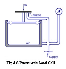
·
This back pressure acts on the diaphragm
producing an upward force. Air pressure is regulated until the diaphragm
returns to the pre-loaded position which is indicated by air which comes out of
the nozzle.
· At this stage, the corresponding pressure indicated by the pressure gauge becomes a measure of the applied force when calibrated.
Related Topics