Chapter: Basic Electrical and electronics : Digital Electronics
Logic Gates
LOGIC GATES
All digital systems are made from a few basic digital circuits that
we call logic gates. These circuits perform the basic logic functions that we
will describe in this session. The physical realization of these logic gates
has changed over the years from mechanical relays to electronic vacuum tubes to
transistors to integrated circuits containing thousands of transistors.
In this appendix you will learn:
Definitions of the basic gates in terms of truth tables and logic equations DeMorgan's Theorem
How gates defined in terms of positive and
negative logic are related To use multiple-input gates
How to perform a sum of products and a product
of sums design from a truth table specification
1 The Three Basic Logic Gates
Much of a computer’s hardware is comprised of digital logic
circuits. Digital logic circuits are built from just a handful of primitive
elements, called logic gates, combined in various ways.
In a digital logic circuit, only two values may be present. The
values may be −5 and + 5 volts. Or the values may be 0.5 and 3.5 volts. Or the
values may be… you get the picture. To allow consideration of all of these
possibilities, we will say that digital logic circuits allow the presence of
two logical values: 0 and 1.
So, signals in a digital logic circuit take on the values of 0 or
1. Logic gates are devices which compute functions of these binary signals.
The AND Gate
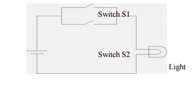
Consider
the circuit below which consists of a battery, a light, and two switches in
series:
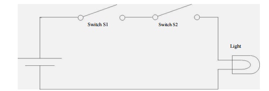
When will the light turn on? It should be clear that the light will
turn on only if both switch S1 and switch S2 are shut.
It is quite likely that you encounter the and operation in some
shape or form hundreds of times each day. Consider the simple action of
withdrawing funds from your checking account at an ATM. You will only be able
to complete the transaction if you have a checking account and you have money
in it. The ATM will only permit the transaction if you have your ATM card and
you enter your correct 4-digit PIN. To enter the correct PIN, you have to enter
the first digit correctly and enter the second digit correctly and enter the
third digit correctly and enter the fourth digit correctly.
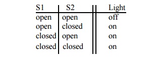
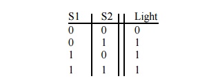
Returning
to the circuit above, we can represent the light's operation using a table:
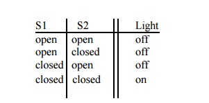
The
switch is a binary device: it can be open or closed. Let’s represent these two
states as 0 and 1. Likewise, the light is a binary device with two states: off
and on, which we will represent as 0 and 1. Rewriting the table above with this
notation, we have:
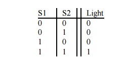
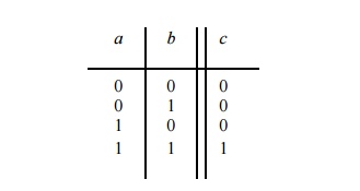
This
table, which displays the output for all possible combinations of the input, is
termed the truth table for the AND operation. In a computer, this and
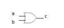
functionality is implemented with a circuit called an AND gate. The simplest
AND gate has two inputs and one output and is represented pictorially by the
symbol:
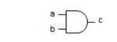
where the inputs have been labeled a and b, and the output
has been labeled c. If both inputs
are 1 then the output is 1. Otherwise, the output is 0.
We represent the and operation by using either the multiplication
symbol (i.e., “ ∙ “) or by writing the inputs together. Thus, for the AND gate shown
above, we would write the output c as
c = a b or as c = ab. This would be pronounced: “c = a and b.”
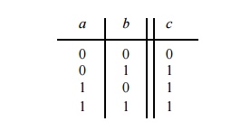
The truth table for the AND gate is shown below. The output c = ab is equal to 1 if and only if
(iff) a is 1 and b is 1. Otherwise, the output is 0.
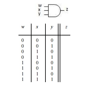
AND
gates can have more than one input (however, an AND gate always has just a
single output). Let’s consider a three-input AND gate:
The OR Gate
Now consider
the circuit shown below, that has 2 switches in parallel.
It is evident that the light will turn on when either switch S1
is shut or switch S2 is shut or both are shut.
It is quite likely that you encounter the or operation in some
shape or form hundreds of times each day. Consider the simple action of sitting
on your couch at home at two in the morning studying for your Digital Logic
class. Your phone will ring if you get a call from Alice or from Bob. Your
home’s security alarm will go off if the front door opens or the back door
opens. You will drink a cup of coffee if you are drowsy or you are thirsty.
We can
represent the light's operation using a table
Changing
the words open and off to 0 and the words shut and on to 1 and the table becomes:
This is
the truth table for the OR operation. This or functionality is implemented with
a circuit called an OR gate. The simplest OR gate has two inputs and one output
and is represented pictorially by the symbol:
If either or both inputs are 1, the output is
1. Otherwise, the output is 0.
We represent the or operation by using the addition symbol. Thus,
for the OR gate above, we would write the output c as c = a + b. This would be
pronounced: “c = a or b.”
The truth table for the OR gate is shown below. The output is 1 if a is 1 or b is 1; otherwise, the output is 0.
The NOT Gate
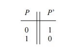
The last of our basic logic gates is the NOT gate. The NOT gate
always has one input and one output. If the input is 1, the output is 0. If the
input is 0, the output is 1. This operation— chaging the value of the binary
input—is called complementation, negation or inversion. The mathematical symbol
for negation is an apostrophe. If the input to a NOT gate is P, the output,
termed the complement, is denoted as P’.
The pictorial symbol for a NOT gate is intended to depict an
amplifier followed by a bubble, shown below. Sometimes the NOT operation is
represented by just the bubble, without the amplifier.
The truth table for the NOT gate is shown
below:
Three New Gates
Three
new gates, NAND, NOR, and Exclusive-OR, can be formed from our three basic
gates: NOT, AND, and OR.
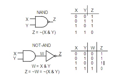
NAND Gate
The
logic symbol for a NAND gate is like an AND gate with a small circle (or
bubble) on the output.we see that the output of a NAND gate is 0 (low) only if
both inputs are 1 (high) . The NAND gate is equivalent to an AND gate followed
by an inverter (NOT-AND).
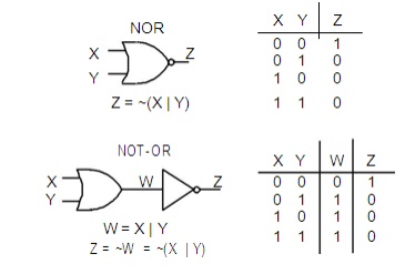
NOR Gate
The
logic symbol for a NOR gate is like an OR gate with a small circle (or bubble)
on the output. From the truth table .we see that the output of a NOR gate is 1
(high) only if both inputs are 0 (low). The NOR gate is equivalent to an OR
gate followed by an inverter (NOT-OR), as shown by the two truth tables.
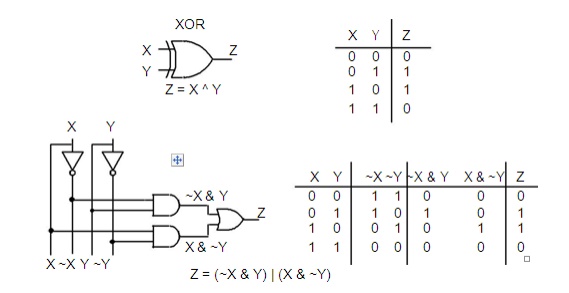
Exclusive-OR Gate.
The XOR gate logic symbol is like an OR gate symbol with an extra
curved vertical line on the input. From the truth table .we see that the output
Z of an XOR gate is 1 (true or high) if either input, X or Y, is 1 (true or
high), but not both. The output Z will be zero if both X and Y are the same
(either both 1 or both 0).
The
equation for the XOR gate is given as Z = X ^ Y. In this book we will use the
symbol ^ as the XOR operator. Sometimes the symbol or the dollar sign $ is used
to denote Exclusive-OR. We will use the symbol ^ because that is the symbol
recognized by the Verilog software used to program a CPLD.
Related Topics