Chapter: Measurements and Instrumentation : Storage and Display Devices
LCD & Dot Matrix Display
LCD & Dot Matrix Display
LIQUID CRYSTAL DISPLAY
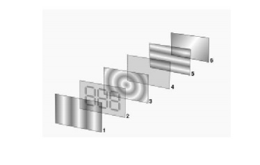
Reflective twisted nematic liquid crystal display.
1. Polarizing filter film with a vertical axis to polarize light as it enters.
2. Glass substrate with ITO electrodes. The shapes of these electrodes will determine the shapes that will appear when the LCD is turned ON. Vertical ridges etched on the surface are smooth.
3. Twisted nematic liquid crystal.
4. Glass substrate with common electrode film (ITO) with horizontal ridges to line up with the horizontal filter.
5. Polarizing filter film with a horizontal axis to block/pass light.
6. Reflective surface to send light back to viewer. (In a backlit LCD, this layer is replaced with a light source.)
A liquid crystal display (LCD) is a thin, flat electronic visual display that uses the light modulating properties of liquid crystals (LCs). LCs do not emit light directly.
They are used in a wide range of applications including: computer monitors, television, instrument panels, aircraft cockpit displays, signage, etc. They are common in consumer devices such as video players, gaming devices, clocks, watches, calculators, and telephones. LCDs have displaced cathode ray tube (CRT) displays in most applications. They are usually more compact, lightweight, portable, less expensive, more reliable, and easier on the eyes.They are available in a wider range of screen sizes than CRT and plasma displays, and since they do not use phosphors, they cannot suffer image burn-in. LCDs are more energy efficient and offer safer disposal than CRTs.
Overview
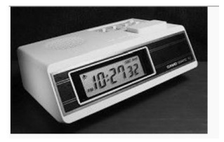
LCD alarm clock
Each pixel of an LCD typically consists of a layer of molecules aligned between two transparent electrodes, and two polarizing filters, the axes of transmission of which are (in most of the cases) perpendicular to each other. With no actual liquid crystal between the polarizing filters, light passing through the first filter would be blocked by the second (crossed) polarizer. In most of the cases the liquid crystal has double refraction.
The surface of the electrodes that are in contact with the liquid crystal material are treated so as to align the liquid crystal molecules in a particular direction. This treatment typically consists of a thin polymer layer that is unidirectionally rubbed using, for example, a cloth. The direction of the liquid crystal alignment is then defined by the direction of rubbing. Electrodes are made of a transparent conductor called Indium Tin Oxide (ITO).
Before applying an electric field, the orientation of the liquid crystal molecules is determined by the alignment at the surfaces of electrodes. In a twisted nematic device (still the most common liquid crystal device), the surface alignment directions at the two electrodes are perpendicular to each other, and so the molecules arrange themselves in a helical structure, or twist. This reduces the rotation of the polarization of the incident light, and the device appears grey. If the applied voltage is large enough, the liquid crystal molecules in the center of the layer are almost completely untwisted and the polarization of the incident light is not rotated as it passes through the liquid crystal layer. This light will then be mainly polarized perpendicular to the second filter, and thus be blocked and the pixel will appear black. By controlling the voltage applied across the liquid crystal layer in each pixel, light can be allowed to pass through in varying amounts thus constituting different levels of gray. This electric field also controls (reduces) the double refraction properties of the liquid crystal.
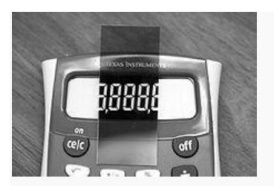
LCD with top polarizer removed from device and placed on top, such that the top and bottom polarizers are parallel.
The optical effect of a twisted nematic device in the voltage-on state is far less dependent on variations in the device thickness than that in the voltage-off state. Because of this, these devices are usually operated between crossed polarizers such that they appear bright with no voltage (the eye is much more sensitive to variations in the dark state than the bright state). These devices can also be operated between parallel polarizers, in which case the bright and dark states are reversed. The voltage-off dark state in this configuration appears blotchy, however, because of small variations of thickness across the device.
Both the liquid crystal material and the alignment layer material contain ionic compounds. If an electric field of one particular polarity is applied for a long period of time, this ionic material is attracted to the surfaces and degrades the device performance. This is avoided either by applying an alternating current or by reversing the polarity of the electric field as the device is addressed (the response of the liquid crystal layer is identical, regardless of the polarity of the applied field).
When a large number of pixels are needed in a display, it is not technically possible to drive each directly since then each pixel would require independent electrodes. Instead, the display is multiplexed. In a multiplexed display, electrodes on one side of the display are grouped and wired together (typically in columns), and each group gets its own voltage source. On the other side, the electrodes are also grouped (typically in rows), with each group getting a voltage sink. The groups are designed so each pixel has a unique, unshared combination of source and sink. The electronics, or the software driving the electronics then turns on sinks in sequence, and drives sources for the pixels of each sink.
ILLUMINATION
LCD panels produce no light of their own, they require an external lighting mechanism to be easily visible. On most displays, this consists of a cold cathode fluorescent lamp that is situated behind the LCD panel. Passive-matrix displays are usually not backlit, but active-matrix displays almost always are, with a few exceptions such as the display in the original Gameboy Advance. Recently, two types of LED backlit LCD displays have appeared in some televisions as an alternative to conventional backlit LCDs. In one scheme, the LEDs are used to backlight the entire LCD panel. In another scheme, a set of green red and blue LEDs is used to illuminate a small cluster of pixels, which can improve contrast and black level in some situations. For example, the LEDs in one section of the screen can be dimmed to produce a dark section of the image while the LEDs in another section are kept bright. Both schemes also allows for a slimmer panel than on conventional displays.
Passive-matrix and active-matrix addressed LCDs
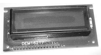
A general purpose alphanumeric LCD, with two lines of 16 characters. LCDs with a small number of segments, such as those used in digital watches and pocket calculators, have individual electrical contacts for each segment. A external dedicated circuit supplies an electric charge to control each segment. This display structure is unwieldy for more than a few display elements.
Small monochrome displays such as those found in personal organizers, electronic weighing scales, older laptop screens, and the originalGameboy have a passive-matrix structure employing super-twisted nematic (STN) or double-layer STN (DSTN) technology (the latter of which addresses a colour-shifting problem with the former), and colour-STN (CSTN) in which colour is added by using an internal filter. Each row or column of the display has a single electrical circuit. The pixels are addressed one at a time by row and column addresses. This type of display is called passive-matrix addressed because the pixel must retain its state between refreshes without the benefit of a steady electrical charge. As the number of pixels (and, correspondingly, columns and rows) increases, this type of display becomes less feasible. Very slow response times and poor contrast are typical of passive-matrix addressed LCDs.
Monochrome passive-matrix LCDs were standard in most early laptops (although a few used plasma displays). The commercially unsuccessful Macintosh Portable (released in 1989) was one of the first to use an active-matrix display (though still monochrome), but passive-matrix was the norm until the mid-1990s, when colour active-matrix became standard on all laptops.
High-resolution colour displays such as modern LCD computer monitors and televisions use an active matrix structure. A matrix of thin-film transistors (TFTs) is added to the polarizing and colour filters. Each pixel has its own dedicated transistor, allowing each column line to access one pixel. When a row line is activated, all of the column lines are connected to a row of pixels and the correct voltage is driven onto all of the column lines. The row line is then deactivated and the next row line is activated. All of the row lines are activated in sequence during a refresh operation. Active-matrix addressed displays look "brighter" and "sharper" than passive-matrix addressed displays of the same size, and generally have quicker response times, producing much better images.
ACTIVE MATRIX TECHNOLOGIES
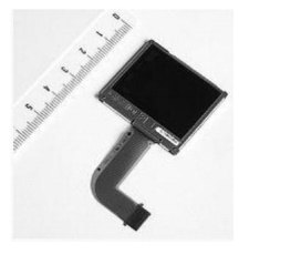
A Casio 1.8 in colour TFT liquid crystal display which equips the SonyCyber-shot DSC-P93A
Twisted nematic (TN)
Twisted nematic displays contain liquid crystal elements which twist and untwist at varying degrees to allow light to pass through. When no voltage is applied to a TN liquid crystal cell, the light is polarized to pass through the cell. In proportion to the voltage applied, the LC cells twist up to 90 degrees changing the polarization and blocking the light's path. By properly adjusting the level of the voltage almost any grey level or transmission can be achieved.
In-plane switching (IPS)
In-plane switching is an LCD technology which aligns the liquid crystal cells in a horizontal direction. In this method, the electrical field is applied through each end of the crystal, but this requires two transistors for each pixel instead of the single transistor needed for a standard thin-film transistor (TFT) display. Before LGEnhanced IPS was introduced in 2009, the additional transistors resulted in blocking more transmission area, thus requiring a brighter backlight, which consumed more power, and made this type of display less desirable for notebook computers. This newer, lower power technology can be found in the AppleiMac, iPad, and iPhone 4, as well as the Hewlett-Packard EliteBook 8740w. Currently Panasonic is using an enhanced version eIPS for their large size LCD-TV products.Advanced fringe field switching (AFFS) Known as fringe field switching (FFS) until 2003, advanced fringe field switching is a technology similar to IPS or S-IPS offering superior performance and colour gamut with high luminosity. AFFS is developed by HYDIS TECHNOLOGIES CO.,LTD, Korea (formally Hyundai Electronics, LCD Task Force). AFFS-applied notebook applications minimize colour
In 2004, HYDIS TECHNOLOGIES CO.,LTD licenses AFFS patent to Japan's Hitachi Displays. Hitachi is using AFFS to manufacture high end panels in their product line. In 2006, HYDIS also licenses AFFS to Sanyo Epson Imaging Devices Corporation.
HYDIS introduced AFFS+ which improved outdoor readability in 2007.
Vertical alignment (VA)
Vertical alignment displays are a form of LCDs in which the liquid crystal material naturally exists in a vertical state removing the need for extra transistors (as in IPS). When no voltage is applied, the liquid crystal cell remains perpendicular to the substrate creating a black display. When voltage is applied, the liquid crystal cells shift to a horizontal position, parallel to the substrate, allowing light to pass through and create a white display. VA liquid crystal displays provide some of the same advantages as IPS panels, particularly an improved viewing angle and improved black level
Blue Phase mode
Blue phase LCDs do not require a liquid crystal top layer. Blue phase LCDs are relatively new to the market, and very expensive because of the low volume of production. They provide a higher refresh rate than normal LCDs, but normal LCDs are still cheaper to make and actually provide better colours and a sharper image
Military use of LCD monitors
LCD monitors have been adopted by the United States of America military instead of CRT displays because they are smaller, lighter and more efficient, although monochrome plasma displays are also used, notably for their M1 Abrams tanks. For use with night vision imaging systems a US military LCD monitor must be compliant with MIL-L-3009 (formerly MIL-L-85762A). These LCD monitors go through extensive certification so that they pass the standards for the military. These include MIL-STD-901D - High Shock (Sea Vessels), MIL-STD-167B - Vibration (Sea Vessels), MIL-STD-810F – Field Environmental Conditions (Ground Vehicles and Systems),MIL-STD-461E/F –EMI/RFI(Electromagnetic nterference/Radio Frequency Interference), MIL-STD-740B – Airborne/Structureborne Noise, and TEMPEST - Telecommunications Electronics Material Protected from Emanating Spurious Transmissions
Quality control
Some LCD panels have defective transistors, causing permanently lit or unlit pixels which are commonly referred to as stuck pixels or dead pixels respectively. Unlike integrated circuits (ICs), LCD panels with a few defective transistors are usually still usable. It is claimed that it is economically prohibitive to discard a panel with just a few defective pixels because LCD panels are much larger than ICs, but this has never been proven. Manufacturers' policies for the acceptable number of defective pixels vary greatly. At one point, Samsung held a zero-tolerance policy for LCD monitors sold in Korea. Currently, though, Samsung adheres to the less restrictive ISO 13406-2 standard. Other companies have been known to tolerate as many as 11 dead pixels in their policies. Dead pixel policies are often hotly debated between manufacturers and customers. To regulate the acceptability of defects and to protect the end user, ISO released the ISO 13406-2 standard. However, not every LCD manufacturer conforms to the ISO standard and the ISO standard is quite often interpreted in different ways. LCD panels are more likely to have defects than most ICs due to their larger size. For example, a 300 mm SVGA LCD has 8 defects and a 150 mm wafer has only 3 defects. However, 134 of the 137 dies on the wafer will be acceptable, whereas rejection of the LCD panel would be a 0% yield. Due to competition between manufacturers quality control has been improved. An SVGA LCD panel with 4 defective pixels is usually considered defective and customers can request an exchange for a new one. Some manufacturers, notably in South Korea where some of the largest LCD panel manufacturers, such as LG, are located, now have "zero defective pixel guarantee", which is an extra screening process which can then determine "A" and "B" grade panels. Many manufacturers would replace a product even with one defective pixel. Even where such guarantees do not exist, the location of defective pixels is important. A display with only a few defective pixels may be unacceptable if the defective pixels are near each other. Manufacturers may also relax their replacement criteria when defective pixels are in the center of the viewing area. LCD panels also have defects known as clouding (or less commonly mura), which describes the uneven patches of changes in luminance. It is most visible in dark or black areas of displayed scenes
ZERO-POWER (BISTABLE) DISPLAYS
The zenithal bistable device (ZBD), developed by QinetiQ (formerly DERA), can retain an image without power. The crystals may exist in one of two stable orientations ("Black" and "White") and power is only required to change the image. ZBD Displays is a spin-off company from QinetiQ who manufacture both grayscale and colour ZBD devices. A French company, Nemoptic, has developed the BiNem zero-power, paper-like LCD technology which has been mass-produced in partnership with Seiko since 2007.
This technology is intended for use in applications such as Electronic Shelf Labels, E-books, E-documents, E-newspapers, E-dictionaries, Industrial sensors, Ultra-Mobile PCs, etc.
Kent Displays has also developed a "no power" display that uses Polymer Stabilized Cholesteric Liquid Crystals (ChLCD). A major drawback of ChLCD screens are their slow refresh rate, especially at low temperatures. Kent has recently demonstrated the use of a ChLCD to cover the entire surface of a mobile phone, allowing it to change colours, and keep that colour even when power is cut off. In 2004 researchers at the University of Oxford demonstrated two new types of zero-power bistable LCDs based on Zenithal bistable techniques. Several bistable technologies, like the 360° BTN and the bistable cholesteric, depend mainly on the bulk properties of the liquid crystal (LC) and use standard strong anchoring, with alignment films and LC mixtures similar to the traditional monostable materials. Other bistable technologies (i.e. Binem Technology) are based mainly on the surface properties and need specific weak anchoring materials. distortion while maintaining its superior wide viewing angle for a professional display. Colour shift and deviation caused by light leakage is corrected by optimizing the white gamut which also enhances white/grey reproduction.
Comparison of the OLPC XO-1 display (left) with a typical colour LCD. The images show 1×1 mm of each screen. A typical LCD addresses groups of 3 locations as pixels. The XO-1 display addresses each location as a separate pixel.
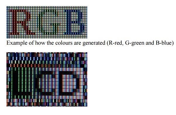
In colour LCDs each individual pixel is divided into three cells, or subpixels, which are coloured red, green, and blue, respectively, by additional filters (pigment filters, dye filters and metal oxide filters). Each subpixel can be controlled independently to yield thousands or millions of possible colours for each pixel. CRT monitors employ a similar 'subpixel' structures via phosphors, although the electron beam employed in CRTs do not hit exact subpixels. The figure at the left shows the twisted nematic (TN) type of LCD.
Related Topics