Chapter: Digital Electronics : Sequential Circuits
JK Flip-Flops
JK FLIP-FLOPS:
Proposed
to get rid of the forbidden I/P problem of R-S
I) J=1, K=0:
(a) Let Q=1, → R=0, S=0
→ Hold
state of R-S → Q=1, Q =1 Q = 0
Q = 0 Q
= 0
ii)
J=0,
K=1 Q=0, using a similar analysis
iii)
J=K=0 ≡
Hold state
A JK
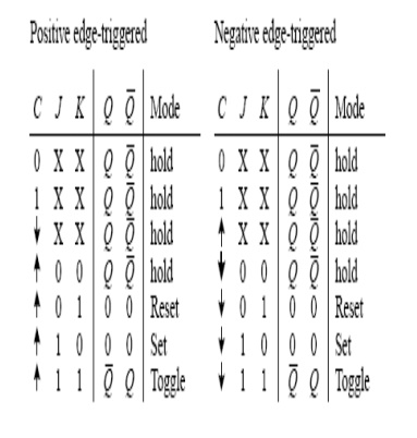
flip-flop resembles an SR flip-flop, where J acts like S and K acts like R.
Likewise, it has a set mode (J = 1, K = 0), a reset mode ( J = 0, K = 1), and a
hold mode ( J = 0, K = 0). However, unlike the SR flip-flop, which has an
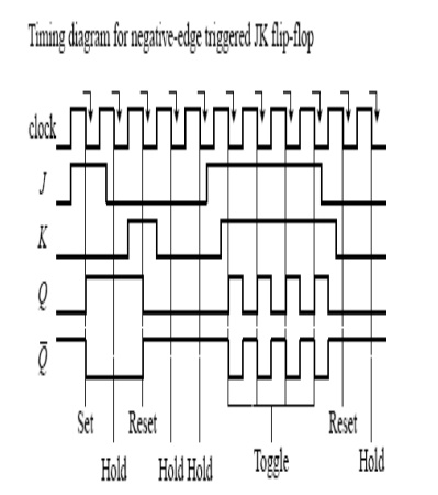
indeterminate mode when S = 1, R = 1, the JK flip-flop has a toggle mode when J
= 1, K = 1. Toggle means that the Q and Q_ outputs switch to their opposite
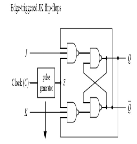
states at each active clock edge. To make a JK flip-flop, modify the SR flip
flop’s internal logic circuit to include two cross-coupled feedback lines
between the output and input. This modification, however, means that the JK flip-flop
cannot be level-triggered; it can only be edge-triggered or pulse-triggered.
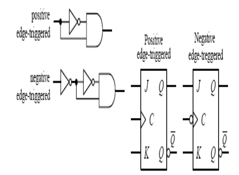
Fig shows how you can create edge-triggered flip-flops based on the cross-NAND
SR edge triggered flip-flop.
Related Topics