Chapter: Mechanical : Automobile Engineering : Engine Auxiliary Systems Ignition System
Introduction of Ignition System
Introduction of Ignition System
·
For petrol engine - Battery ignition system , Magneto ignition
system Injection system
·
For diesel engine - Fuel supply system.
Battery
ignition system:
Battery
ignition system has the following
elements
·
Primary Ignition Circuit(low voltage)
·
Battery
·
Ignition switch
·
Primary windings of coil
·
Contact breaker
·
capacitor
·
Secondary Ignition Circuit ( high voltage)
·
Secondary windings of coil
·
Distributor cap and rotor (if the vehicle is so
equipped)
·
Spark plug wires &
·
Spark plugs
IGNITION SYSTEM – Magneto
System Ignition Switch Distribution Contact Breaker Coil Magneto Condenser
Power Generation Spark Generation Magneto Unit Rotor Arm
IGNITION SYSTEM –
Dynamo/Alternator System Dynamo/ Alternator Distributor Contact Breaker Coil
Ignition Switch Secondary Windings Primary Windings Condenser Battery
Ignition Switch Coil Packs IGNITION SYSTEM –
Electronic Systems Control Unit Timing Sensor Timing Disc Engine Speed Sensing
Unit Alternator Battery
In all spark ignition engines
which work on the Gasoline either 2-Stroke or 4-Stroke cycle principle and
utilize a carburetor or fuel injection system, the combustion of the air-fuel
mixture is initiated by an electric spark.
The term ‘Spark
Ignition’ means that a brief electric arc is produced between the electrodes of a
spark plug, the energy for which is derived from an external power source. In
most cases this power source is the vehicle battery, which is constantly being
supplemented by the alternate while the vehicle is mobile.
A different method of ignition is
employed in diesel engines. This is called ‘compression ignition’
and relies on the fact that when air compressed, its temperature rises. In
diesel engines,
compression ratio of between 16:1 and 25:1 are common, and at
the end of a compression the temperature of the trapped air is sufficiently
high to ignite the diesel fuel that is sprayed into the cylinder at the
appropriate time.
The functions of ignition system
The functions of the coil ignition systems in general use on
motor vehicle may be divided into three areas. These are:
·
Production of the high voltage necessary to
produce a spark at the plug gap.
·
Distribute the spark to all the cylinders at
proper time based on the firing order.
·
Varying the timing of the spark depending on the
various operating conditions of the engine like cranking time, varying speed
and load, so that the best performance is obtained from the engine under all
operating conditions.
Mechanism of Ignition
It must be remembered that vehicle battery voltages are
usually 12 volt or 24 volt and this value is too low to produce a heavy spark
at the plug gap in a cylinder under compression. For this reason one of the
major functions of the battery ignition system is to raise the battery voltage
to the required level and then apply it to spark plugs.
This process is correctly initiated in the primary circuit and
completed in the secondary winding of the ignition coil. Depending on the type
of engine and the conditions existing in the cylinders, a voltage of between
5,000 to 20,000 volts is required and this is called the ionizing voltage
or firing voltage.
This firing voltage forces the electrons to jump between the
electrodes of the spark plug in the gap to produce the required spark. The
electric spark has sufficient heat energy to ignite the air-fuel mixture which
later continues to burn itself.
The conventional coil ignition
system
Inductive ignition systems: that uses an ignition coil
to perform the step up transformer action and to increase the electrical
voltage. The ignition coils of the inductive ignition systems operate on the
principle of electromagnetic induction (EMI) irrespective of whether it is
triggered by contact breakers or by electronic triggering units.
Note:
As a reminder of the principle of EMI, a voltage will be
induced into a coil whenever the following factors are present:
(a)
a magnetic field
(b)
a set of conductors
(c)
a relative movement between the magnetic field and
conductors.
The
factors affecting the operation of the Ignition system.
` The factors that determine the value of the
voltages induced into the ignition coil windings during the ignition cycle are:
(a) The
strength of the magnetic field.
The stronger the magnetic field produced in the
coil primary winding, the greater the possibility of producing a high secondary
voltage.
(b)
The number of conductors on the secondary winding
being cut by the magnetic field. This
isimportant when considering the
voltages produced in both coil windings during the ignition cycle.
(c) The speed
of relative movement between the magnetic field and the conductors. The faster
the magnetic field can be made to cut the conductors, the higher will be the
value of voltage induced into the coil windings.
Construction
of the Ignition coil
The source of the high voltage pulses of current produced in
the inductive ignition system is in the ignition coil. The coil stores the
energy in the magnetic field around the primary winding and at the required
instant of ignition, transforms it into a pulse of high voltage current in the
secondary
winding. From here it is delivered to the correct
spark plug via the high tension (HT) cables.
This
‘Inductive
storage device’ may vary in design between certain manufacturers, but in
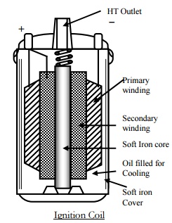
general the most common construction is as shown in figure below.
This
coil contains a rod shaped, laminated soft iron core at its centre, and the
soft iron cover surrounds both primary and secondary windings. Both of these
soft iron components are used to intensify and maximize the effect of the
primary magnetic field and thus, the energy stored. The iron core must be
laminated to minimize the effects of eddy currents that are produced during
operation and so keep to a minimum the heat developed. The outer soft iron cover
is slotted to allow circulation of the oil filling which is used for cooling
purposes.
Around the laminated core, the secondary winding is wounded.
This consists of many turns of very fine insulated copper wire (generally in
the vicinity of 20,000 turns). One end of this winding is connected to the HT
outlet of the coil via the laminated iron core which it used as the pick-up
point for this connection. The other end is connected to the positive (+) low
tension primary terminal.
Over the top of the secondary winding the primary winding is
wounded with the insulation. The primary winding consisting of a few hundred
turns of relatively heavy insulated copper wire. The ends of the primary
winding are connected to the two low tension, or primary terminals. A reason
for placing the primary winding over the secondary is that it is in this coil,
which caries the full primary circuit current (approximately 2 ampere in
standard systems), the secondary winding generates the heat and by placing it
thus, the cooling oil is given ready access to it.
A ceramic insulator at the base of the coil supports the core
and winding and at the top is a plastic-type insulator which provides a
location point for the high-tension and primary terminals. This top insulator
is sealed into the outer case to prevent the loss of coolant oil or the energy
of moisture.
Operation of an Ignition coil
Electromagnetic induction is the effect of creating the
voltage in a conductor by means of relative movement between the conductor and
a magnetic field. In the ignition coil the conductors remain stationary and the
magnetic field is moved across them. To develop these necessary conditions, the
first requirement in the ignition oil is the production of a magnetic field.
This is the function of the primary winding.
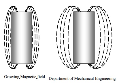
When
the ignition switch is closed, the primary winding of the coil is connected to
the positive terminal of the vehicle battery. Now, if the primary circuit is
completed through the contact breaker points a current will flow in the
circuit, creating a magnetic field in the coil around the soft iron core. This
magnetic field grows outwards from the core until it has reached maximum value
and the core is fully magnetized and ceases to grow further.
To provide the very high voltage necessary to create a spark
across the plug gap, the secondary winding has a very large number of turns.
NOTE: The ratio of the number of secondary turns to the number of primary turns
is very large – approximately 100:1. The effect of this high
ration is to produce a very high voltage in the secondary winding when the
magnetic field is collapsed rapidly across it as the contact breaker points are
opened.
To understand the operation of the ignition coil, it is
necessary to have the knowledge of the effect of winding insulated wire into
the form of a coil and then passing a current through it. In earlier chapters
of this course, an explanation was given of how a magnetic field forms around a
wire when current flows through it.
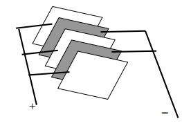
Construction
The
construction of a capacitor is quite simple. It is made of two strips of
metallised paper, separated by a thin dielectric (insulator), generally of
waxed paper or plastic, both rolled tightly together and fitted into a metal
container. An insulated flexible lead is attached to one of the metallised
plates and brought out for connection to the insulated side of the contacts.
The other metallised plate is attached to the metal container which has
facilities for connecting it to a good earth either inside or outside the
distributor, thus effectively connecting the capacitor across, or in parallel,
with the points.
As
a general statement it can be said that a capacitor is a device which has
the ability to store an electrical
charge. When a capacitor is
‘charged’, each plate will hold an equal
but opposite charge. That is the
plate connected to
the negative side
of the circuit
will acquire a negative charge,
and the plate connected to the positive side of the circuit, a positive
charge. Once these opposite charges are
stored on the plates, they will attract each other through the separating
dielectric, and thus tend to prevent the charge escaping or leaking away.
NOTE:
The loss of electrical charge from a capacitor is termed the capacitor’s
leakage. Among the tests applied to a capacitor is a test for
leakage, which must be below a certain rate of loss.
Removing
the charge from a capacitor is called discharging it. This is accomplished by
connecting a conductor across its plates. The excess electrons are attracted
from the negatively charged plate to the positively electrons are attracted
from the negatively charged plate to the positively charged plate. The electron
flow continues until such time as both charges equalize, i.e. there is no
potential difference between the plates.
The
factors affecting the capacity of a capacitor:
(a)
The area of the plates holding the charges and the
number of plates used.
(b)
The distance the plates are separated, i.e. the
thinner the dielectric, the greater the attractive force between the charges,
and therefore the higher the capacity.
(c)
The type of dielectric, e.g. plastic, mica, paper,
air, etc.
Unit
of Capacitor
The amount of charge a capacitor
can hold is termed its capacitance (symbol C) which is measured in a unit
called the farad (symbol F). Since the farad is a large quantity and it is
difficult to have such a big capacitor in real time, the capacitors are generally
measured by micro farad (Symbol µF)
Automotive capacitors are in the
vicinity of 0.20 to 0.30 microfarads (one microfarad = 10-6 farads,
or 1 millionth of a farad).
The
operation of a capacitor in an ignition circuit is relatively simple, but tends
to appear complex because of the number of events, or changes, that occur
simultaneously. The following explanation presents these changes as a logical,
sequential set of events.
CIRCUIT
OF THE IGNITION CIRCUIT
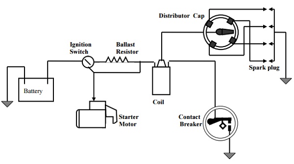
A simple circuit shown above can illustrate the position of
the major components of an ignition system. With the
ignition switch ‘on’: when the breaker contacts initially close, a
current
commences
to flow in the primary circuit and the magnetic field builds up relatively
slowly, due to the self induced voltage that is developed at this time
During this ‘closed circuit period’ of the ignition
cycle, the capacitor is in parallel with the
breaker
contacts which are closed at this time. As the distributor shaft continues its
rotation the cam lobe lift the breaker gently to open the contacts.
It takes a certain number of degrees of distributor shaft
rotation and therefore a measurable period of time for this to occur.
When the contacts are open and instantly a resistance is
presented to the primary circuit because of this contact gap. The primary
current is interrupted and the magnetic field is starting to collapse. The
current produced by the self induced voltage has to enter the plates of the
capacitor. Since the high resistance will be induced across the contacts due to
their separation and it will naturally take the low resistance path.
Capacitor function
When the contacts gap is slowly widening and the self induced
voltage is rapidly rising towards the 200-300 volt level. The capacitor is
rapidly charging up. As the capacitor reaches the
fully
charged state, the contacts have opened to such a degree that even this high
voltage cannot jump the gap and so the primary circuit
currents comes to an ‘instant halt’.
This sudden stopping of the primary current, produced by the
action of the capacitor, gives an extremely fast collapse of the magnetic
field. The mutually induced voltage, generated in the secondary winding at this
instant will be very high. Since the secondary winding has about 100 times as
many turns as the primary winding, the secondary voltage will be about 100
times higher than the primary voltage (200 to 300 volts).
The
secondary voltage at this instant is fed out through the HT circuit to the
correct spark plug where it ionizes the plug gap and forms a spark which
ignites the air-fuel mixture. For the period of time of spark duration the
capacitor remains fully charged. After the energy of the secondary circuit has
been expended in the HT spark, the capacitor discharges back through the
battery, ignition switch and coil primary to the opposite plate of the
capacitor, thus recharging it in the reverse direction. The capacitor then
discharges back again to recharge itself in the original direction – but at a
lower value. It continues this oscillating cycle of charge and discharge until
all of the stored energy is dissipated across the resistance of the primary
circuit. The distributor cam continues its rotation, the points close again and
the whole cycle is repeated.
Related Topics