Chapter: Microprocessor and Microcontroller : 8085 Microprocessor
Interrupts and Types of Interrupts in 8085 Microprocessor
Interrupts
Interrupt
is signals send by an external device to the processor, to request the
processor to perform a particular task or work.
ü Mainly in
the microprocessor based system the interrupts are used for data transfer
between the peripheral and the microprocessor.
ü The
processor will check the interrupts always at the 2nd T-state of last machine
cycle.
ü If there
is any interrupt it accept the interrupt and send the INTA (active low) signal
to the peripheral.
ü The
vectored address of particular interrupt is stored in program counter.
ü The
processor executes an interrupt service routine (ISR) addressed in program counter.
ü It
returned to main program by RET instruction.
Types of Interrupts:
It
supports two types of interrupts.
ü Hardware
ü Software
1 Software interrupts:
The
software interrupts are program instructions. These instructions are inserted
at desired locations in a program. The 8085 has eight software interrupts from
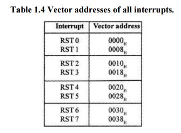
RST 0 to RST 7. The vector address for these interrupts can be calculated as
follows.
ü Interrupt
number * 8 = vector address
ü For RST
5,5 * 8 = 40 = 28H
ü Vector
address for interrupt RST 5 is 0028H
Table 1.4 Vector addresses of all interrupts.
2 Hardware interrupts:
An
external device initiates the hardware interrupts and placing an appropriate
signal at the interrupt pin of the processor. If the interrupt is accepted then
the processor executes an interrupt service routine.
The 8085
has five hardware interrupts
ü TRAP
ü RST 7.5
ü RST 6.5
ü RST 5.5
ü INTR
TRAP:
ü This
interrupt is a non-maskable interrupt. It is unaffected by any mask or
interrupt enable.
ü TRAP bas
the highest priority and vectored interrupt.
ü TRAP
interrupt is edge and level triggered. This means that the TRAP must go high
and remain high until it is acknowledged.
ü In sudden
power failure, it executes a ISR and send the data from main memory to backup
memory.
ü The
signal, which overrides the TRAP, is HOLD signal. (i.e., If the processor
receives HOLD and TRAP at the same time then HOLD is recognized first and then
TRAP is recognized).
ü There are
two ways to clear TRAP interrupt.
1. By
resetting microprocessor (External signal)
2. By giving
a high TRAP ACKNOWLEDGE (Internal signal)
RST 7.5:
ü The RST
7.5 interrupt is a maskable interrupt.
ü It has
the second highest priority.
ü It is
edge sensitive. ie. Input goes to high and no need to maintain high state until
it recognized.
ü Maskable
interrupt. It is disabled by,
1.DI
instruction
2.System
or processor reset. 3.After reorganization of interrupt.
ü Enabled
by EI instruction.
RST 6.5 and 5.5:
ü The RST
6.5 and RST 5.5 both are level triggered. . ie. Input goes to high and stay
high until it recognized.
ü Maskable
interrupt. It is disabled by,
1.DI, SIM
instruction 2.System or processor reset.
3.After
reorganization of interrupt.
ü Enabled
by EI instruction.
ü The RST
6.5 has the third priority whereas RST 5.5 has the fourth priority.
INTR:
INTR is a
maskable interrupt. It is disabled by,
1.DI, SIM
instruction
2.System
or processor reset. 3.After reorganization of interrupt
ü Enabled
by EI instruction.
ü Non-
vectored interrupt. After receiving INTA (active low) signal, it has to supply
the address of ISR.
ü It has
lowest priority.
ü It is a
level sensitive interrupts. ie. Input goes to high and it is necessary to
maintain high state until it recognized.
The
following sequence of events occurs when INTR signal goes high.
1. The 8085
checks the status of INTR signal during execution of each instruction.
2. If INTR
signal is high, then 8085 complete its current instruction and sends active low
interrupt acknowledge signal, if the interrupt is enabled.
3. In
response to the acknowledge signal, external logic places an instruction OPCODE
on the data bus. In the case of multibyte instruction, additional interrupt
acknowledge machine cycles are generated by the 8085 to transfer the additional
bytes into the microprocessor.
4. On
receiving the instruction, the 8085 save the address of next instruction on
stack and execute received instruction.
SIM and RIM for interrupts:
ü The 8085
provide additional masking facility for RST 7.5, RST 6.5 and RST 5.5 using SIM
instruction.
ü The status
of these interrupts can be read by executing RIM instruction.
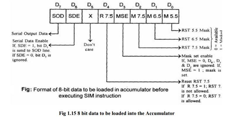
ü The
masking or unmasking of RST 7.5, RST 6.5 and RST 5.5 interrupts can be
performed by moving an 8-bit data to accumulator and then executing SIM
instruction.
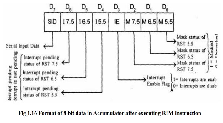
ü The
status of pending interrupts can be read from accumulator after executing RIM
instruction.
ü When RIM
instruction is executed an 8-bit data is loaded in accumulator, which can be
interpreted as shown in fig.
Related Topics