Chapter: Microprocessor and Microcontroller : 8051 Microcontroller
Instruction set and Assembly language programming of 8051 Microcontroller
8051 Instructions
8051 has
about 111 instructions. These can be grouped into the following categories
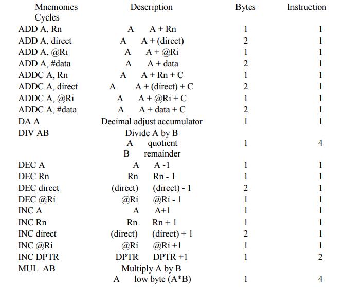
1. Arithmetic
Instructions
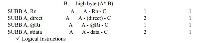
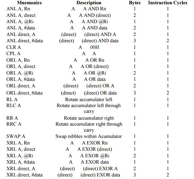
2. Logical
Instructions
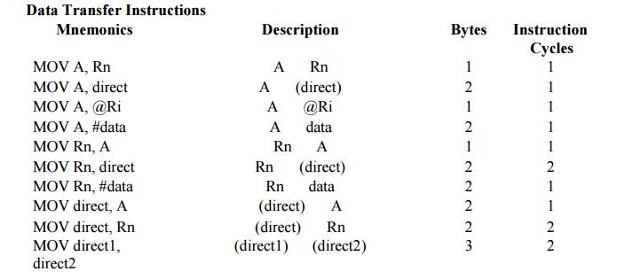
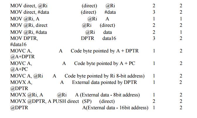
3. Data
Transfer instructions
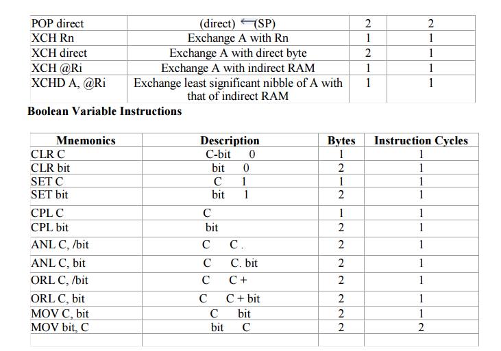
4. Boolean
Variable Instructions
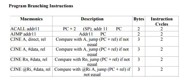
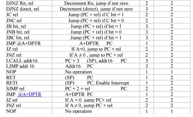
5. Program
Branching Instructions
The
following nomenclatures for register, data, address and variables are used
while write instructions.
A: Accumulator
B: "B"
register
C: Carry bit
Rn:
Register R0 - R7 of the currently selected register bank
Direct:
8-bit internal direct address for data. The data could be in lower 128bytes of
RAM (00 - 7FH) or it could be in the special function register (80 - FFH).
@Ri:
8-bit external or internal RAM address available in register R0 or R1. This is
used for indirect addressing mode.
#data8:
Immediate 8-bit data available in the instruction. #data16: Immediate 16-bit
data available in the instruction.
Addr11:
11-bit destination address for short absolute jump. Used by instructions AJMP
& ACALL. Jump range is 2 kbyte (one page).
Addr16:
16-bit destination address for long call or long jump.
Rel: 2's
complement 8-bit offset (one - byte) used for short jump (SJMP) and all
conditional jumps.
bit:
Directly addressed bit in internal RAM or SFR
ü Arithmetic
Instructions
Assembly language Programming
Character
transmission using a time delay:
A program
shown below takes the character in 'A' register, transmits it, delays for
transmission time, and returns to the calling program. Timer-1 is used to set
the baud rate, which is 1200 baud in this program
The delay
for one character transmission (in Mode 1 i.e.10 bits) is 10/2400 = 0.00833
seconds
Or, 8.33
milliseconds
Hence
software delay of 10ms is used.
Timer-1
generates a baud rate close to 1200. Using a 12MHz crystal, the reload value is
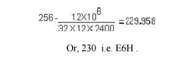
This
gives rise to an actual baud rate of 1202. SMOD is programmed to be 0.
Assembly
language Program is as follows
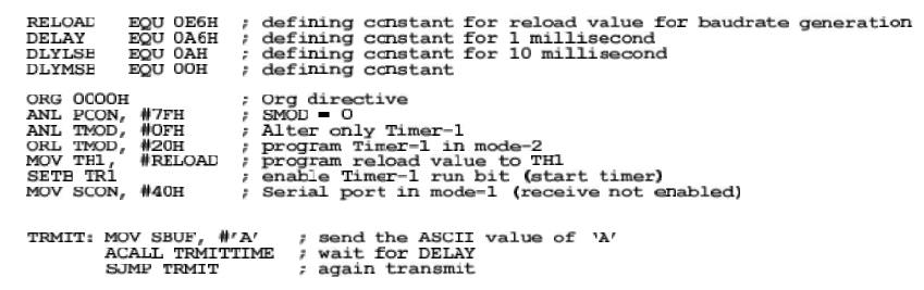
; Code to
wait for the transmission to complete
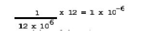
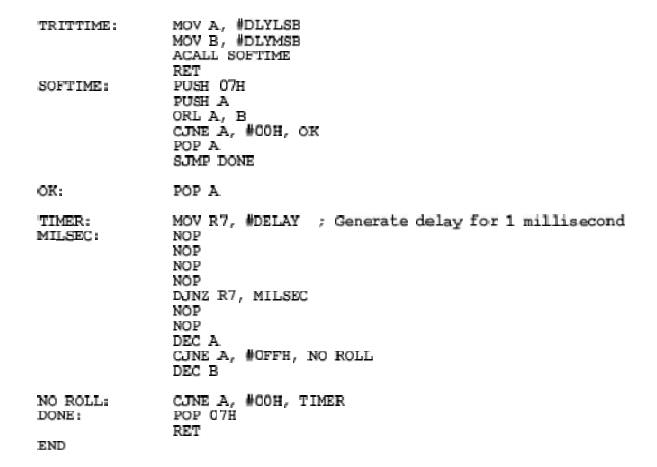
The
subroutine TRMITTIME generates a delay of about 10ms. With a clock of 12MHz,
one instruction cycle time is
The loop
"MILSEC" generates a delay of about 1 x 10⁻³ sec. This
gets executed 10 times for a total delay of 10 x 10-3 sec or 10ms
Related Topics