Chapter: Electrical and electronics : Circuit Theory : Transient Response For DC Circuits
Important Short Questions and Answers: Transient Response For DC Circuits
1. Define response.
The current flowing through or voltage across branches in the circuit is called response.
2. Define steady state response.
The behavior of voltage or current does not change with time is called steady state response
3. Define transient response.
The voltage or current are changed from one transient state to another transient state is called transient response.
4. Define natural response.
The response determined by the internal energy stored in the network is called natural response. It depends upon the type of elements, their size and the interconnection of elements. The response is independent of the source.
Energy may be stored internally in the form of electric field of capacitor or in the magnetic field of an inductor.
The natural response also known as transient response.
5. Define forced response.
The response determined by the application of external energy source is called forced response. The external energy source of forcing function may be direct voltage or current, sinusoidal source, exponential function, ramp function.
6. What is transient?
The state (or condition) of the circuit from the transient of switching to attainment of steady state is called transient state or simply transient.
7. Why transient occurs in electric circuits?
The inductance will not allow the sudden change in current and the capacitance will not allow sudden change in voltage. Hence inductive and capacitive circuits (or in general reactive circuits0transient occurs during switching operation.
8. Define time constant of RL circuit.
The time constant of RL circuit is defined as the ratio of inductance and resistance of the circuit.
(Or)
The time constant of RL circuit is defined as the time taken by the current through the inductance to reach 63.21%of its final steady state value.
(Or)
The time constant of RL circuit is defined as the time taken by the voltage across inductance to fall to 36.79% of its initial value.
(Or)
The time constant of RL circuit is defined as the time taken by current through the inductance to reach steady state value if initial rate of rise is maintained.
9. Define time constant of RC circuit.

The time constant of RC circuit is defined as the product of capacitance and resistance of the circuit.
(Or)
The time constant of RC circuit is defined as the time taken by the voltage across the capacitance to reach 63.21%of its final steady state value.
(Or)
The time constant of RC circuit is defined as the time taken by the current through the capacitance to fall to 36.79% of its initial value.
(Or)
The time constant of RL circuit is defined as the time taken by the voltage across the capacitance to reach steady state value if initial rate of rise is maintained.
10.Sketch the transient current and voltages of RL circuit.
11.Sketch the transient current and voltages of RC circuit.
12.Voltage across capacitor cannot change instantaneously. Justify.
If the voltage across capacitance changes instantaneously then the current IL=a which is impossible
since it requires infinite power. Hence voltage across capacitor cannot change instantaneously.
13. Current through an inductor cannot change instantaneously. Justify.

If the current through inductor changes instantaneously then the current VL= α which is impossible since it requires infinite power. Hence current through inductor cannot change instantaneously.
14.What is the initial condition of the elements capacitor and inductor that have no initial energy storage?
The capacitor acts as a short circuit and the inductor acts as an open circuit.
15.What is the final condition of the elements inductor and capacitor?
The capacitor acts as an open circuit and the inductor acts as a short circuit.
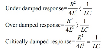
16. Write the conditions for response of an RLC series network?
17. Sketch the response of RLC circuit.
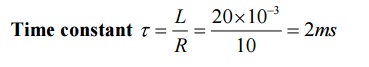
18. What is the time constant of RL circuit with R=10Ω and L=20mH.
19. What is the time constant of RL circuit.
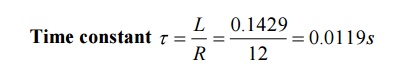
20. What is the time constant of RC circuit with R=10KΩ and C=40μF.

21. What is the time constant of RC circuit.

22. What is damping ratio?
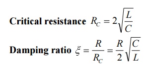
The ratio of resistance of the circuit and resistance for critical damping is called damping ratio.
23. What is critical damping?
The critical damping is the condition of the circuit at which the oscillations in the response are just eliminated. This is possible by increasing the value of resistance in the circuit..
24. What is critical resistance?
The critical resistance is the value of the resistance of the circuit to achieve critical damping.
25. Write the expression for critical resistance and damping ratio of RLC series circuit.
26. What is natural and damped frequency?

The response of under damped circuit is oscillatory with a frequency of wn and these oscillations are damped as t tends to infinity. The frequency of damped oscillatory response is called damped frequency.
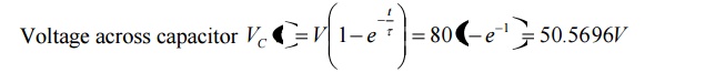
27. A RC series circuit is excited by a dc voltage source 80V by closing the switch at t=0.Determine the voltage across the capacitor in a time of one constant.
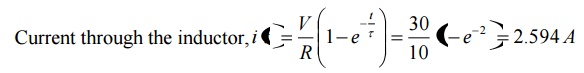
28. A RL series circuit with R=10 Ω is excited by a dc voltage source 30V by closing the switch at t=0.Determine the current in the circuit at t=2
29. A RLC series circuit with R=5 Ω is excited by a dc voltage source 10V by closing the switch at t=0.Draw the initial and final condition of the circuit.
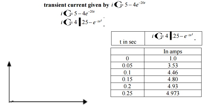
30. Sketch the transient current given by
31. A pure inductance of 1.273 mH is connected in series with a pure resistance of 30 Ω. If the frequency of the sinusoidal supply is 5 kHz and the p.d. across the 30Ω resistor is 6 V, determine the value of the supply voltage and the voltage across the 1.273 mH inductance. Draw the phasor diagram.
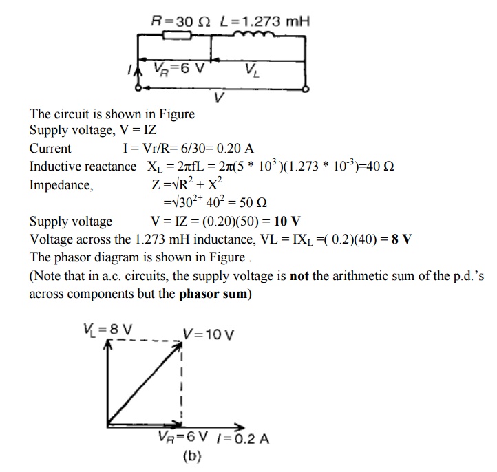
The phasor diagram is shown in Figure .
(Note that in a.c. circuits, the supply voltage is not the arithmetic sum of the p.d.’s across components but the phasor sum)
Related Topics