Chapter: Optical Communication and Networking : Fiber Optic Receiver and Measurements
Important Short Questions and Answers: Fiber Optic Receiver and Measurements
FIBER OPTIC RECEIVER AND
MEASUREMENTS
1. Define minimum detectable optical power.
It is
defined as the optical power necessary to produce a photocurrent of the same
magnitude as the root mean square of the total current.
2. Define quantum noise.
It is not
possible to predict exactly how many electron-hole pairs are generated by a
known optical power incident on the detector is the origin of the type of short
noise called quantum noise.
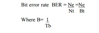
3. What is meant by error rate?
An approach
is to divide the
number Ne of
errors occurring over a
certain time interval t by the number Nt of pulses transmitted during this
interval. This is called either the error rate or the bit error rate.
4. Define quantum limit
It is possible
to find the minimum received optical power required for a specific bit error
rate performance in a digital system. This minimum received power level is
known as quantum limit.
5. Give the classifications of preamplifiers.
o Low impedence(LZ) preamplifier
o High impedence(HZ) preamplifier
o Transimpedence preamplifier
6. What is meant by excess noise factor?
The ratio
of the actual noise generated in an avalanche photodiode to the noise that
would exist if all carrier pairs were multiplied by exactly m is called the
excess noise factor (F).
7. What is meant by inter symbol interference
(ISI)?
ISI
results from pulse spreading in the optical fibre. The presence of this energy
in adjacent time slots results in an interfering signal. Hence it is called
ISI.
8.
Give the
advantages of Pin photodiodes.
•
Very low reverse bias is necessary
•
High quantum efficiency
•
Large bandwidth
•
Low noise level
9.
What do
you mean by thermal noise?
Thermal
noise is due to the random motion of electrons in a conductor. Thermal noise
arising from the detector load resistor and from the amplifier electronics tend
to dominate in applications with low signal to noise ratio.
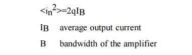
10. Give the equation for mean square shot noise.
The mean
square shot noise is given by
11.
Define
multiplication M .
The
multiplication M for all carriers generated in
the photodiode is defined by
M=IM/IP
IM : average
value of the total multiplied output current
IP : primary unmultiplied photocurrent
12. What is current mode of operation of
photodiode?
In photo
conducting mode, the photocurrent is
slightly dependent on the reverse
bias. For a constant reverse bias, the current is linear.
This is called current mode of operation of the photodiode.
13. What are the system requirements?
The
following are the key system requirements.
•
The desired or possible transmission distance
•
The data rate or channel bandwidth
•
Bit error rate (BER)
14.
What are
splices? What are the requirements of splices?
The splices
are generally permanent
fiber joints, whereas
connectors are temporary fiber joints. Splicing is a sort of
soldering. The requirements of splices are:
•
Should cause low attenuation
•
Should be strong & light in weight
•
Should have minimum power loss
•
Should be easy to install
15.
What are
the methods of fiber splicing?
There are
3 methods of fiber splicing. They are:
•
Electric arc fusion splicing or fusion splicing
•
Mechanical splicing
•
V-groove splicing or loose tube splicing
16.
What are
connectors? What are the types of connectors?
The
connectors are used to join the optical sources as well as detectors to the
optical fiber temporarily. They are also
used to join two optical fibers. The 2
major types of connectors are:
•
Lensed type expanded beam connector
•
Ferrule type connector
17.
What are
the requirements of a good connector?
The
requirements of a good connector are as follows:
o Low
loss
o Repeatability
o Predictability
o Ease of assembly and use o Low cost & reliability
o
Compatibility
18.
Give the
2 analysis that are used to ensure system performance?
The 2
analysis that are used to ensure system performance are:
•
Link power budget analysis
•
Rise time budget analysis
19.
Explain
briefly about link power budget analysis?
In the
optical power loss model for a pt-to-pt link, the optical power rxed at the
photo detector depends on the amount of light coupled into the fiber &
losses occurring in the fiber at the connectors & splices. The link loss
budget is derived from the sequential loss contribution of each element in the
link.
Loss=10 log (Pout) / (Pin)
The total
optical power loss is,
PT = PS -
PR
20. Give the range of system margin in link power
budget?
The
system margin is usually (6-8) db. A
positive system margin ensures proper operation of the circuit. A negative
value indicates that insufficient power will reach the detector to achieve the
required bit error rate, BER.
21. What are the system components of system rise
time?
The 4
basic system components that contribute to the system rise time are:
o Transmitter (source) rise time
o Receiver rise time
o Material
dispersion time of the fiber
o Modal
dispersion time of the fiber link
All these
4 basic elements may significantly limit system speed.
22. Why the attenuation limit curve slopes
downwards to the right?
As the
minimum optical power required at the rxer for a given BER becomes higher for
increasing data rates, the attenuation limit curve slopes downward to the
right.
23. What are the noise effects on system
performance?
The main
penalties are modal noise, wavelength chirp, spectral broadening, mode-
partition noise.
24. Define modal noise?
It arises
when the light from a coherent laser is coupled in to a multimode fiber
operating at 400Mbps and higher. It mainly occurs due to mechanical vibrations
and fluctuations in the frequency of the optical source.
25. What are the measures to avoid modal noise?
The
measures are
•
use LEDs
•
use LASER having more longitudinal modes
•
use a fiber with large numerical aperture
•
use a single mode fiber
26.
Define
mode partition noise?
The mode partition
noise is associated with intensit y fluctuations in the longitudinal modes of a
laser diode. It becomes more pronounced for the higher bit rates.
27. What is meant by chirping?
It means
that the dynamic line broadening (line broadening is a frequency chirp) in the
laser which oscillates in the single longitudinal mode under CW operation when
the injection current is intensity modulated.
28. What is the best way to minimize the chirping?
It is to
choose the laser emission wavelength close to the zero-dispersion of the
wavelength of the fiber.
29. What is reflection noise?
It is the
optical power that gets reflected at the refractive index discontinuities such
as in splices, couplers and filters, or connectors. The reflected signals can
degrade both the transmitter and receiver performance.
30. What are the effects of reflection noise in
high speed systems?
They
cause optical feedback which leads to optical instabilities that may lead to
inter symbol interference and intensity noise.
GLOSSARY
1. Minimum detectable optical power.
It is
defined as the optical power necessary to produce a photocurrent of the same
magnitude as the root mean square of the total current.
2. Quantum noise.
It is not
possible to predict exactly how many electron-hole pairs are generated by a
known optical power incident on the detector is the origin of the type of short
noise called quantum noise.
3. Error rate
An
approach is to divide the number Ne of errors occurring over a certain time
interval t by the number Nt of pulses transmitted during this interval. This is
called either the error rate or the bit error rate.
4. Quantum limit
It is
possible to find the minimum received optical power required for a specific bit
error rate performance in a digital system. This minimum received power level
is known as quantum limit.
5. Excess noise factor.
The ratio
of the actual noise generated in an avalanche photodiode to the noise that
would exist if all carrier pairs were multiplied by exactly m is called the
excess noise factor (F).
6. Inter symbol interference (ISI).
ISI
results from pulse spreading in the optical fibre. The presence of this energy
in adjacent time slots results in an interfering signal. Hence it is called
ISI.
7. Thermal noise.
Thermal
noise is due to the random motion of electrons in a conductor. Thermal noise
arising from the detector load resistor and from the amplifier electronics tend
to dominate in applications with low signal to noise ratio.
8. Multiplication M .
The
multiplication M for all carriers generated in
the photodiode is defined by
M = IM/
IP
IM :
average value of the total multiplied output current
IP:
primary unmultiplied photocurrent
9. Current mode of operation of photodiode.
In photo
conducting mode, the photocurrent is slightly dependent on the reverse bias.
For a constant reverse bias, the current is linear. This is called current mode
of operation of the photodiode.
10. Splices.
The
splices are generally permanent fiber joints, whereas connectors are temporary
fiber joints. Splicing is a sort of soldering.
11. Connectors.
The
connectors are used to join the optical sources as well as detectors to the optical
fiber temporarily. They are also used to join two optical fibers. The 2 major
types of connectors are:
•
Lensed type expanded beam connector
•
Ferrule type connector
12.
Link
power budget analysis.
In the
optical power loss model for a pt-to-pt link, the optical power rxed at the
photo detector depends on the amount of light coupled into the fiber &
losses occurring in the fiber at the connectors & splices.
13. Modal noise.
It arises
when the light from a coherent laser is coupled in to a multimode fiber
operating at 400Mbps and higher. It mainly occurs due to mechanical vibrations
and fluctuations in the frequency of the optical source.
14. Mode partition noise.
The mode
partition noise is associated with intensity fluctuations
in the longitudinal modes of a laser diode. It becomes more pronounced for the
higher bit rates.
15. Chirping
It means
that the dynamic line broadening (line broadening is a frequency chirp) in the
laser which oscillates in the single longitudinal mode under CW operation when
the injection current is intensity modulated.
16. Reflection noise.
It is the
optical power that gets reflected at the refractive index discontinuities such
as in splices, couplers and filters, or connectors. The reflected signals can
degrade both the transmitter and receiver performance.
Related Topics