Chapter: Embedded and Real Time Systems : Computing Platform and Design Analysis
I/O Devices
I/O
DEVICES:
Some of
these devices are often found as on-chip devices in micro-controllers; others
are generally implemented separately but are still commonly used. Looking at a
few important devices now will help us understand both the requirements of
device interfacing.
Timers and Counters:
Timers and
counters are distinguished from one another largely by their use, not
their logic. Both are built from adder logic with registers to hold the
current value, with an increment input that adds one to the current register
value.
However,
a timer has its count connected to a periodic clock signal to measure time
intervals, while a counter has its count input connected to an aperiodic signal
in order to count the number of occurrences of some external event. Because the
same logic can be used for either purpose, the device is often called a counter/timer.
Figure
2.6 shows enough of the internals of a counter/timer to illustrate its
operation. An n-bit counter/timer
uses an n-bit register to store the
current state of the count and an array of half
subtractors to decrement the count
when the count signal is asserted.
Combinational
logic checks when the count equals zero; the done output signals the zero count. It is often useful to be able
to control the time-out, rather than require exactly 2n events to occur. For this purpose, a reset register provides the
value with which the count register is to be loaded.
The
counter/timer provides logic to load the reset register. Most counters provide
both cyclic and acyclic modes of operation. In the cyclic mode, once the
counter reaches the done state, it is
automatically reloaded and the counting process continues. In acyclic mode, the
counter/timer waits for an explicit signal from the microprocessor to resume
counting.

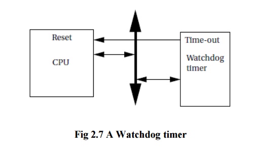
A watchdog
timer is an I/O device that is used for internal operation of a system.
As shown in Figure 2.7, the watchdog timer is connected into the CPU bus and
also to the CPU’s reset line.
The CPU’s
software is designed to periodically reset the watchdog timer, before the timer
ever reaches its time-out limit. If the watchdog timer ever does reach that
limit, its time-out action is to reset the processor. In that case, the
presumption is that either a software flaw or hardware problem has caused the
CPU to misbehave. Rather than diagnose the problem, the system is reset to get
it operational as quickly as possible.
A/D and D/A Converters
Analog/digital (A/D) and digital/analog (D/A) converters (typically
known as
ADCs and DACs, respectively) are often used to interface non digital devices
to embedded systems.
The
design of A/D and D/A converters themselves is beyond the scope of this book;
we concentrate instead on the interface to the microprocessor bus. Because A/D
conversion requires more complex circuitry, it requires a somewhat more complex
interface.
Analog/digital
conversion requires sampling the analog input before converting it to digital
form. A control signal causes the A/D converter to take a sample and digitize
it.
There are
several different types of A/D converter circuits, some of which take a
constant amount of time, while the conversion time of others depends on the
sampled value. Variable-time converters provide a done signal so that the
microprocessor knows when the value is ready.
A typical
A/D interface has, in addition to its analog inputs, two major digital inputs.
A data port allows A/D registers to be read and written, and a clock input
tells when to start the next conversion.
D/A
conversion is relatively simple, so the D/A converter interface generally
includes only the data value. The input value is continuously converted to
analog form.
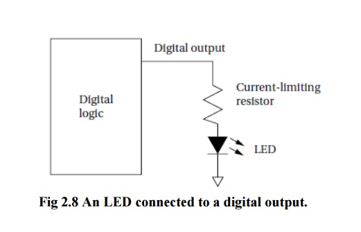
LEDs
Light-emitting
diodes (LEDs) are often used as simple displays by themselves,
and arrays of LEDs may form the basis of more complex displays. Figure 2.8
shows how to connect an LED to a digital output.
A resistor
is connected between the output pin and the LED to absorb the voltage
difference between the digital output voltage and the 0.7 V drop across the
LED. When the digital output goes to 0, the LED voltage is in the devices off
region and the LED is not on.
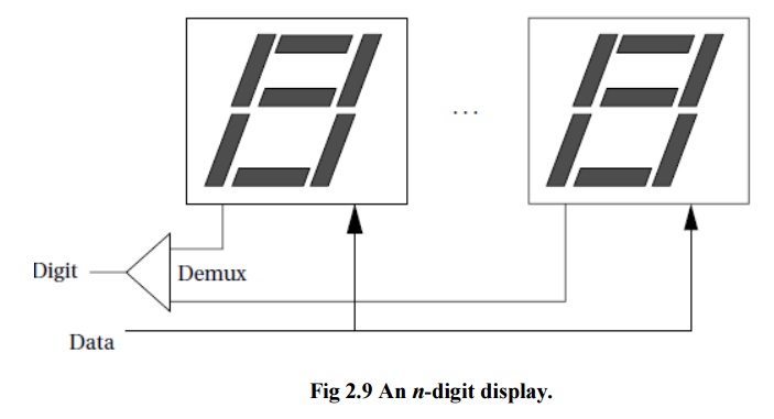
Displays
A display
device may be either directly driven or driven from a frame buffer. Typically,
displays with a small number of elements are driven directly by logic, while
large displays use a RAM frame buffer.
The n-digit array, shown in Figure 2.9, is a
simple example of a display that is usually directly driven. A single-digit
display typically consists of seven segments; each segment may be either an LED
or a liquid
crystal display (LCD) element.
Display
relies on the digits being visible for some time after the drive to the digit
is removed, which is true for both LEDs and LCDs.
The digit
input is used to choose which digit is currently being updated, and the
selected digit activates its display elements based on the current data value.
The
display’s driver is responsible for repeatedly scanning through the digits and
presenting the current value of each to the display.
A frame
buffer is a RAM that is attached to the system bus. The microprocessor
writes values into the frame buffer in whatever order is desired.
The
pixels in the frame buffer are generally written to the display in raster
order (by tradition, the screen is in the fourth quadrant) by reading
pixels sequentially.
Many
large displays are built using LCD. Each pixel in the display is formed by a
single liquid crystal.
Early LCD
panels were called passive matrix because they relied on a two-dimensional grid of
wires to address the pixels. Modern LCD panels use an active matrix system that
puts a transistor at each pixel to control access to the LCD. Active matrix
displays provide higher contrast and a higher-quality display.
Touchscreens
A touchscreen
is an input device overlaid on an output device. The touchscreen registers the
position of a touch to its surface. By overlaying this on a display, the user
can react to information shown on the display.
The two
most common types of touchscreens are resistive and capacitive. A resistive
touchscreen uses a two-dimensional voltmeter to sense position. As shown in
Figure 2.10, the touchscreen consists of two conductive sheets separated by
spacer balls. The top conductive sheet is flexible so that it can be pressed to
touch the bottom sheet.
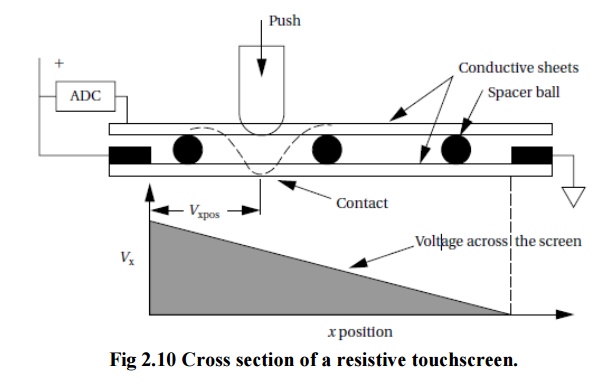
A voltage
is applied across the sheet; its resistance causes a voltage gradient to appear
across the sheet. The top sheet samples the conductive sheet’s applied voltage
at the contact point. An analog/digital converter is used to measure the
voltage and resulting position.
The
touchscreen alternates between x and y position sensing by alternately
applying horizontal and vertical voltage gradients.
Related Topics