Chapter: Mechanical and Electrical : Power Plant Engineering : Diesel,Gas Tubine and Combined Cycle Power Plants
Gas turbine cycle with reheater
Gas turbine cycle with reheater
Reheat gas
C : Compressor
CC:
Combustion chamber G : Generator
f : Fuel
HPT: High
Pressure turbine LPT: Low pressure turbine
RCC: Reheat combustion chamber

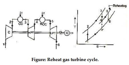
Figure: Reheat gas turbine cycle.
Reheat gas turbine cycle arrangement is shown in figure. In
order to maximize the work available from the simple gas turbine cycle one of
the option is to increase enthalpy of fluid entering gas turbine and extend its
expansion upto the lowest possible enthalpy value. This can also be said in
terms of pressure and temperature values i.e., inject fluid at high pressure
and temperature into gas turbine and expand upto lowest possible pressure
value. Upper limit at inlet to turbine is limited by metallurgical limits while
lower pressure is limited to near atmospheric pressure in case of open cycle.
For further increasing in net work output the positive work may be increased by
using multistage expansion with reheating in between. In multistage expansion
is divided into parts and after part expansion working fluid may be reheated
for getting larger positive work in left out expansion. For reheating another
combustion chamber may be used.
Here in the arrangement shown ambient air enters
compressor and compressed air at high pressure leaves at 2. Compressed air is
injected into combustion chamber for increasing its temperature upto desired
turbine inlet temperature at state3. High pressure and high temperature fluid
enters high pressure turbine (HPT) for first phase of expansion and expanded
gases leaving at 4 are sent to reheat combustion chamber (reheater) for being
further heated. Thus reheating is a kind of energizing the working fluid. Assuming
perfect reheating (in which temperature after reheat is same as temperature
attained in first combustion chamber), the fluid leaves at state 5 and enters
low pressure turbine (LPT) for remaining expansion upto desired pressure value.
Generally temperature after reheating at state 5, is less than temperature at
state 3. In the absence of reheating the expansion process within similar
pressure limits goes upto state 4’.Thus reheating offers an obvious advantage
of work output increase since constant pressure lines T-S diagram diverge
slightly with increasing entropy, the
total work of the two stage turbine
is greater that that of single expansion from state 3 to state 4’,i.e.(T –T
) + (T –T ) > (T –T ’).
Here it may be noted that the heat addition also increases
because of additional heat supplied for reheating. Therefore, despite the
increase in network due to reheating the cycle thermal efficiency would not
necessarily increases. Let us now carry out air standard cycle analysis.
Network output in reheat cycle, W net,
reheat = WHPT + WLPT - WC
WHPT = m (h3 –h4), WLPT = m(h5 –h6),
WC = m(h2 –h1)
W net, reheat = m {(h3 –h4) + (h5 –h6)
–(h2 –h1)}
W net , reheat = m cp {(T3 –T4) + (T5
–T6) –(T2 - T1)}
Assuming,
T3 = T5
W net, reheat = m cp {(2T3 –T4) –T6 –(T2 –T1)}
Qin = m cp {(T3 –T2) + (T5 –T4)
W
h =
reheat
Qin
Related Topics