Chapter: Power Electronics : Power Semi Conductor Devices
GTO (Gate turn off thyristor)
GTO (Gate turn off thyristor)
A gate turn off thyristor is a pnpn device. In which it can be turned ON like an ordinary SCR by a positive gate current. However it can be easily turned off by a negative gate pulse of appropriate magnitude eexistence.
The salient features of GTO are:
1. GTO turned on like conventional SCR and is turned off by a negative gate signal of sufficient magnitude.
2. It is a non latching device.
3. GTO reduces acoustic and electromagnetic noise.
It has high switching frequency and efficiency.A gate turn off thyristor can turn on like an ordinary thyristor but it is turn off by negativegate pulse of appropriate magnitude.
Disadvantage
The negative gate current required to turn off a GTO is quite large that is 20% to 30 % of anode current
Advantage
It is compact and cost less
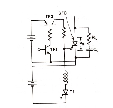
Switching performance
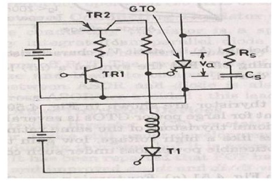
1. For turning ON a GTO first TR1is turned on.
2. This in turn switches on TR2 so that a positive gate current pulse is applied to turn on theGTO.
3. Thyristor T1 is used to apply a high peak negative gate current pulse.
1. Gate turn-on and turn off characteristic Gate turn-on
1. The gate turn on characteristics is similar to a thyristor. Total turn on time consists of delay time, rise time, spread time.
2. The turn on time can be reduced by increasing its forward gate current.
Gate turn off
Turn off time is different for SCR.Turn off characteristics is divied into 3 pd
1. Storage time
2. Fall time
Tq=ts+tf+tt
At normal operating condition gto carries a steady state current.The turn off process starts as soon as negative current is applied after t=0.
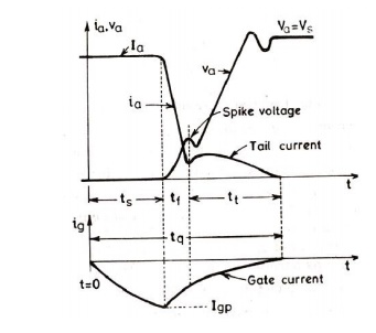
STORAGE TIME
During the storagepd the anode voltage and current remains constant. The gate current rises depending upon the gate circuit impedance and gate applied voltage. The beginning of pd is as soon as negative gate current is applied. The end of storage pd is marked by fall in anode current and rise in voltage, what we have to do is remove the excess carriers. the excess carriers are removed by negative carriers.
FALL TIME
After ts, anode current begins to fall rapidly and anode voltage starts rising. After falling to a certain value, then anode current changes its rate to fall. this time is called fall time
SPIKE IN VOLTAGE
During the time of storage and fall time there is a change in voltage due to abrupt current change.
TAIL TIME
During this time ,the anode current and voltage continues towards the turn off values. The transient overshoot is due to the snubber parameter and voltage stabilizes to steady state value.
Related Topics