Chapter: Optical Communication and Networking : Fiber Optic Receiver and Measurements
Fundamental Receiver Operation
Fundamental Receiver Operation
ü Digital Signal Transmission
ü Error Sources
• Digital Receiver Performance
ü Probability of Error
ü Receiver Sensitivity
ü The Quantum Limit
• Coherent Detection
• Analog Receiver
1. Optical Receiver Operation
Digital Signal Transmission
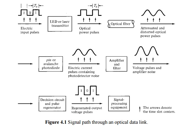
ü A typical digital fiber transmission link is shown in Figure 4.1. The transmitted signal is a two-level binary data stream consisting of either a ‘0’ or a ‘1’ in a bit period Tb.
ü The simplest technique for sending binary data is amplitude-shift keying, wherein a voltage level is switched between on or off values.
ü The resultant signal wave thus consists of a voltage pulse of amplitude V when a binary 1 occurs and a zero-voltage-level space when a binary 0 occurs.
ü An electric current i(t) can be used to modulate directly an optical source to produce an optical output power P(t).
ü In the optical signal emerging from the transmitter, a ‘1’ is represented by a light pulse of duration Tb,whereas a ‘0’ is the absence of any light.
ü The optical signal that gets coupled from the light source to the fiber becomes attenuated and distorted as it propagates along the fiber waveguide. Upon reaching the receiver, either a PIN or an APD converts the optical signal back to an electrical format.
ü A decision circuit compares the amplified signal in each time slot with a threshold level.
ü If the received signal level is greater than the threshold level, a ‘1’ is said to have been received.
ü If the voltage is below the threshold level, a ‘0’ is assumed to have been received.
2. Error Sources
ü Errors in the detection mechanism can arise from various noises and disturbances associates with the signal detection system.
ü The two most common samples of the spontaneous fluctuations are shot noise and thermal noise.
ü Shot noise arises in electronic devices because of the discrete nature of current flow in the device.
ü Thermal noise arises from the random motion of electrons in a conductor.
ü The random arrival rate of signal photons produces a quantum (or shot) noise at the photodetector. This noise depends on the signal level.
ü This noise is of particular importance for PIN receivers that have large optical input levels and for APD receivers.
ü When using an APD, an additional shot noise arises from the statistical nature of the multiplication process. This noise level increases with increasing avalanche gain M.
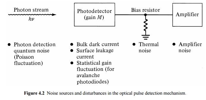
ü Thermal noises arising from the detector load resistor and from the amplifier electronics tend to dominate in applications with low SNR when a PIN photodiode is used.
ü When an APD is used in low-optical-signallevel applications, the optimum avalanche gain is determined by a design tradeoff between the thermal noise and the gain-dependent quantum noise.
ü The primary photocurrent generated by the photodiode is a time-varying Poisson process.
ü If the detector is illuminated by an optical signal P(t), then the average number of electron-hole pairs generated in a time t is
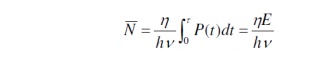
where h is the detector quantum efficiency, hn is the photon energy, and E is the energy received in a time interval .
ü The actual number of electron-hole pairs n that are generated fluctuates from the average according to the Poisson distribution
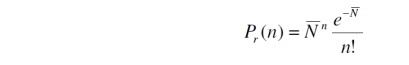
where Pr(n) is the probability that n electrons are emitted in an interval t
ü For a detector with a mean avalanche gain M and an ionization rate ratio k, the excess noise factor F(M) for electron injection is
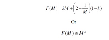
where the factor x ranges between 0 and 1.0 depending on the photodiode material.
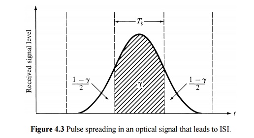
ü A further error source is attributed to intersymbol interference (ISI), which results from pulse spreading in the optical fiber.
ü The fraction of energy remaining in the appropriate time slot is designated by g, so that 1-g is the fraction of energy that has spread into adjacent time slots.
Related Topics