Chapter: Mechanical and Electrical : Power Plant Engineering : Power From Renewable Energy
Fuel cell with Schematic diagram

Fuel
cell with Schematic diagram
A Fuel cell is an electrochemical device in which the
chemical energy of a conventional fuel is converted directly and efficiently
into low voltage, direct-current electrical energy. One of the chief advantages
of such a device is that because the conversion, atleast in theory, can be
carried out isothermally, the Carnot limitation on efficiency does not apply. A
fuel cell is often described as primary battery in which the fuel and oxidizer
are stores external to the battery and fed to it as needed.
Fig.
shows a schematic diagram of a fuel cell. The fuel gas diffuses through the
anode and is oxidized, thus releasing electrons to the external circuit; the
oxidizer diffuses through the cathode and is reduced by the electrons that have
come from the anode by way of the external circuit.
The
fuel cell is a device that keeps the fuel molecules from mixing with the
oxidizer molecules, permitting, however, the transfer of electrons by a
metallic path that may contain a load.
Of the available fuels, hydrogen has so far given the most
promising results, although cells consuming coal, oil or natural gas would be
economically much more useful for large scale applications.
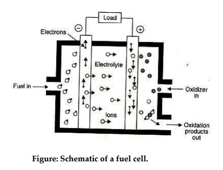
Figure: Schematic of a fuel cell.
Some of the possible reactions are :
Hydrogen/oxygen 1.23
V : 2H2 + O2 -> 2 H2O
Hydrazine 1.56 V N2H4 + O2 -> 2H2O + N2
Carbon (coal) 1.02
V C + O2 -> CO2
Methane 1.05 V CH4 + 2O2 -> CO2
+ 2H2O
Hydrogen-oxygen
cell :
The hydrogen-oxygen devices shown in figure is typical of
fuel cells. It has three chambers separated by two porous electrodes, the anode
and the cathode. The middle chamber between the electrodes is filled with a
strong solution of potassium hydroxide. The surfaces of the electrodes are
chemically treated to repel the electrolyte, so that there is minimum leakage
of potassium hydroxide into the outer chambers. The gases diffuse through the
electrodes, undergoing reactions are show below:
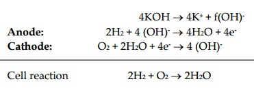
4KOH ® 4K+ + f(OH)-
Anode: 2H2 + 4 (OH)- ® 4H2O + 4e-
Cathode: O2 + 2H2O + 4e- ® 4 (OH)-
Cell reaction 2H2
+ O2 ®
2H2O
The water formed is drawn off from the side. The
electrolyte provides the (OH)- ions needed for the reaction, and
remains unchanged at the end, since these ions are regenerated. The electrons
liberated at the anode find their way to the cathode through the external
circuit. This transfer is equivalent to the flow of a current from the cathode
to the anode.
Such cells when properly designed and operated, have an
open circuit voltage of about 1.1 volt. Unfortunately, their life is limited
since the water formed continuously dilutes the electrolyte. Fuel efficiencies
as high as 60%-70% may be obtained.
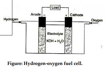
Figure: Hydrogen-oxygen fuel cell.
Related Topics