Chapter: Mechanical : Automobile Engineering : Engine Auxiliary Systems Ignition System
Fuel Injection system for C I engines
Fuel Injection system for C I
engines
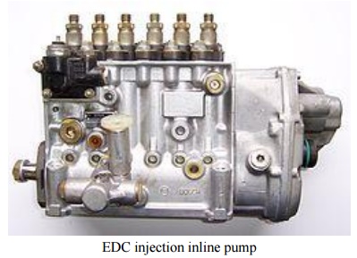
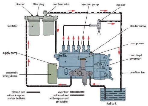
Fuel system components FUEL INJECTION PUMP - Fuel injection
pump sucks fuel from the tank , pressurizes the fuel to approx. 600 - 1000 bar
and sends it to the injectors. Inline FIP - Has separate pumping chambers for
each cylinder Rotary FIP (Distributor pump) - Has one pumping chamber and the
pump distributes to each cylinder as per sequence- firing order INJECTORS -
Inject the high pressure fuel in to each cylinder. FUEL FILTER - Filters the
fuel from dirt & sediments, since the Fuel injection pump requires clean
fuel.
Injection system In the C.I. engine the fuel is injected into
the combustion chamber, it the has to mix thoroughly with the air, ignite and
burn all at the same time. To insure this happens, two types of combustion
chamber have been developed. Direct Injection Indirect Injection
1. Electronic Diesel Control
Electronic Diesel Control
is a diesel engine fuel injection control system for the precise of metering
and delivery in fuel into the combustion chamber of modern diesel engines used trucks
and cars.
The mechanical fly-weight governors of inline and distributor diesel fuel
injection
pumps used to control fuel delivery under a variety of engine loads and
conditions could no longer deal with the ever increasing demands for
efficiency, emission control, power and fuel consumption.
These demands are now primarily fulfilled by the Electronic
Control, the system which provides greater ability for precise measuring, data
processing, operating environment flexibility and analysis to ensure efficient
diesel engine operation. The EDC replaces the mechanical control governor with
an electro-magnetic control device.
2. Components in Electronically
controlled Diesel Supply;
The
EDC is divided into these main groups of components.
· Electronic sensors for registering
operating conditions and
changes. A wide
array
of
physical inputs is converted into electrical signal outputs.
·
Actuators or solenoids which convert the control
unit's electrical output signal into mechanical control movement.
·
ECM (Electronic Control Module ) or Engine ECU
(Electronic Control Unit) with microprocessors which process information from
various sensors in accordance with programmed software and outputs required
electrical signals into actuators and solenoids.
i. Electronic sensors;
·
Injection pump speed sensor - monitors pump
rotational speed
·
Fuel rack position sensor - monitors pump fuel
rack position
·
Charge air pressure sensor - measures pressure
side of the turbocharger
·
Fuel pressure sensor
·
Air cleaner vacuum pressure sensor
·
Engine position sensor
·
Temperature sensors - measure various operating
temperatures
·
Intake temperature
·
Charge air temperature
·
Coolant temperature
·
Fuel temperature
·
Exhaust temperature (Pyrometer)
·
Ambient temperature
·
Vehicle speed sensor - monitors vehicle speed
·
Brake pedal sensor - operates with cruise control,
exhaust brake, idle control
·
Clutch pedal sensor - operates with cruise
control, exhaust brake, idle control
·
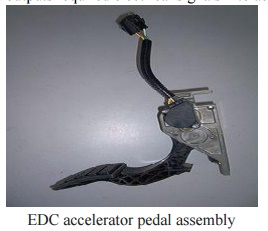
Accelerator pedal sensor.
ii.Electronic Control Unit;
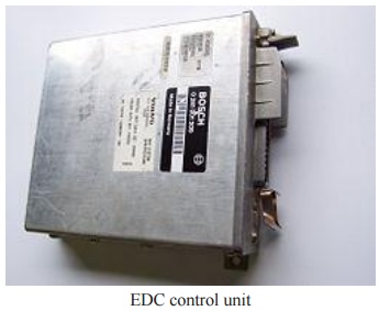
The ECU collects and processes signals from various on-board
sensors. AnECU electronic module contains microprocessors, memory units, analog
to digital converters and output interface units. Depending upon the
parameters, a number of different maps can be stored in the onboard memory.
This allows the ECU to be tailored to the specific engine and
vehicle requirements, depending on the application. The operating software of
the ECU can be adapted for a wide variety of engines and vehicles without the
necessity of hardware modification.
The ECU is usually located in the
cab or in certain cases, in a suitable position in the engine bay where
additional environmental conditions might require cooling of the ECU as well as
a requirement for better dust, heatand vibrations insulation .
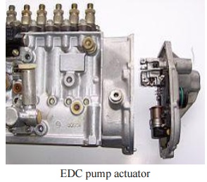
iii. Actuators and Solenoids
Electro-magnetic actuators are
usually located on the fuel pump to transfer electrical signals into mechanical
action in this case fuel rack actuator and or fuel stop solenoid which means
that depending on requests from control unit full fuel or no fuel quantity.
·
Injectors
·
Boost-pressure actuator
·
Intake-duct switchoff
·
Throttle-valve actuator
·
Exhaust-gas recirculation actuator
·
Auxiliary heating
·
A/C compressor
·
Radiator fan
·
Electronic shutoff valve
·
Rail-pressure control valve
·
Diagnosis lamp
Working Principle;
The injection of fuel or the quantity of injected fuel has a
decisive influence on engine starting, idling, power and emissions. The engine
ECU is programmed ("mapped") with relevant data to where the fuel
rack position has an equivalent signal for the amount of fuel being injected.
The driver requests the torque or engine speed requirements
via accelerator pedal potentiometer thereby sending a signal to the engine ECU
which then, depending on its mapping and data collected from various
sensors, calculates in real time the quantity of injected fuel required, thus
altering the fuel rack to the required position. The driver can also input
additional commands such as idle speed increase to compensate e.g. for PTO
operation which can be either variably set or has a preset speed which can be
recalled.
The road speed function can be used to evaluate
vehicle speed and possibly activate a speed limiter (Heavy Vehicles), or
maintain or restore a set speed (cruise control). Further functions can include
exhaust brake operation which, when activated, will result in the fuel pump
rack position being set to zero delivery or idle. The engine ECU can also
interface with various other vehicle systems e.g. traction control and carries
out self monitoring duties and self diagnostic functions to keep the system
working at an optimal level. To ensure the safe operation in case of failure,
the limp home mode functions are also integrated into the system, for e.g.
should the pump speed sensor fail the ECU can use an alternator speed signal
function for engine RPMs counter as a backup signal.
3. Fuel Injector:
Fuel injection is a system for admitting fuel into an internal
combustion engine. It has become the primary fuel delivery system used in
automotive engines, having replaced carburetors during the 1980s and 1990s. A
variety of injection systems have existed since the earliest usage of the
internal combustion engine.
The primary difference between carburetors and fuel injection
is that fuel injection atomizes the fuel by forcibly pumping it through a small
nozzle under high pressure, while a carburetor relies on suction created by
intake air accelerated through a Venturi tube to draw the fuel into the
airstream.
Modern fuel injection systems are designed
specifically for the type of fuel being used. Some systems are designed for
multiple grades of fuel (using sensors to adapt the tuning for the fuel
currently used). Most fuel injection systems are for gasoline or diesel
applications.

Related Topics