Chapter: Digital Signal Processing : IIR Filter Design
Filter Types and Ideal Filter Characteristic
FILTER TYPES AND IDEAL FILTER CHARACTERISTIC
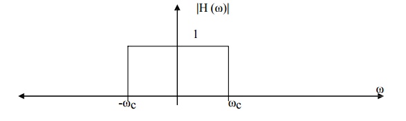
1. Lowpass Filter
A lowpass filter is made up of a passband and a stopband, where the lower frequencies Of the input signal are passed through while the higher frequencies are attenuated.
2. Highpass Filter
A highpass filter is made up of a stopband and a passband where the lower frequencies of the input signal are attenuated while the higher frequencies are passed.

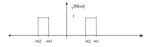
3. Bandpass Filter
A bandpass filter is made up of two stopbands and one passband so that the lower and higher frequencies of the input signal are attenuated while the intervening frequencies are passed.
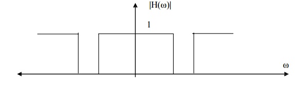
4. Bandstop Filter
A bandstop filter is made up of two passbands and one stopband so that the lower and higher frequencies of the input signal are passed while the intervening frequencies are attenuated. An idealized bandstop filter frequency response has the following
5. Multipass Filter
A multipass filter begins with a stopband followed by more than one passband. By default, a multipass filter in Digital Filter Designer consists of three passbands and
four stopbands. The frequencies of the input signal at the stopbands are attenuated while those at the passbands are passed.
6. Multistop Filter
A multistop filter begins with a passband followed by more than one stopband. By default, a multistop filter in Digital Filter Designer consists of three passbands and two stopbands.
7. All Pass Filter
An all pass filter is defined as a system that has a constant magnitude response for all frequencies.
|H(ω)| = 1 for 0 ≤ ω < ∏
The simplest example of an all pass filter is a pure delay system with system function H(z) = Z-k. This is a low pass filter that has a linear phase characteristic.
All Pass filters find application as phase equalizers. When placed in cascade with a system that has an undesired phase response, a phase equalizers is designed to
compensate for the poor phase characteristic of the system and therefore to produce an overall linear phase response.
IDEAL FILTER CHARACTERISTIC
1. Ideal filters have a constant gain (usually taken as unity gain) passband characteristic and zero gain in their stop band.
2. Ideal filters have a linear phase characteristic within their passband.
3. Ideal filters also have constant magnitude characteristic.
4. Ideal filters are physically unrealizable.
Related Topics