Chapter: Optical Communication and Networking : Fiber Optic Receiver and Measurements
Fiber numerical aperture measurements
Fiber numerical aperture
measurements
The
numerical aperture is an important optical fiber parameter as it affects
characteristics such as the light-gathering efficiency and the normalized
frequency of the fiber (V). This in
turn dictates the number of modes propagating within the fiber (also defining
the singlemode region) which has consequent effects on both the fiber
dispersion (i.e. intermodal) and, possibly, the fiber attenuation (i.e.
differential attenuation of modes). The numerical aperture (NA) is defined for a step index fiber
as:

where ϴa
is the maximum acceptance angle, n1
is the core refractive index and n2
is the cladding refractive index.
It is
assumed that the light is incident on the fiber end face from air with a
refractive index (n0) of unity.
Although Eq. (4.17) may be employed with graded index fibers, the numerical
aperture thus defined represents only the local NA of the fiber on its core axis (the numerical aperture for light
incident at the fiber core axis). The graded profile creates a multitude of
local NAs as the refractive index
changes radially from the core axis
For the
general case of a graded index fiber these local numerical apertures NA(r) at
different radial distances r from the core axis may be defined by:

Therefore,
calculations of numerical aperture from refractive index data are likely to be
less accurate for graded index fibers than for step index fibers unless the
complete refractive index profile is considered. The numerical aperture may be
determined by calculation.
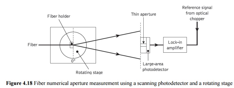
` An
example of an experimental arrangement with a rotating stage is shown in Figure
4.18. A 2 m length of the graded index fiber has its faces prepared in order to
ensure square smooth terminations.
The fiber
output end is then positioned on the rotating stage with its end face parallel
to the plane of the photodetector input, and so that its output is
perpendicular to the axis of rotation. Light at a wavelength of 0.85 μm is
launched into the fiber at all possible angles (overfilling the fiber) using an
optical system similar to that used in the spot attenuation measurements.
The
photodetector, which may be either a small-area device or an apertured
large-area device, is placed 10 to 20 cm from the fiber and positioned in order
to obtain a maximum signal with no rotation (0°). Hence when the rotating stage
is turned the limits of the far-field pattern may be recorded. The output power
is monitored and plotted as a function of angle, the maximum acceptance angle
being obtained when the power drops to 5% of the maximum intensity. Thus the
numerical aperture of the fiber can be obtained from Eq. (4.17).
A less
precise measurement of the numerical aperture can be obtained from the
far-field pattern by trigonometric means. The experimental apparatus is shown
in Figure 4.19.
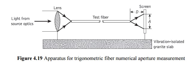
where the
end prepared fiber is located on an optical base plate or slab. Again light is
launched into the fiber under test over the full range of its numerical aperture,
and the farfield pattern from the fiber is displayed on a screen which is
positioned a known distance D from
the fiber output end face. The test fiber is then aligned so that the optical
intensity on the screen is maximized. Finally, the pattern size on the screen A is measured using a calibrated vernier
caliper. The numerical aperture can be obtained from simple trigonometrical
relationships where:
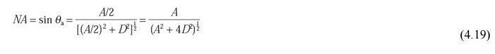
It must
be noted that the accuracy of this measurement technique is dependent upon the
visual assessment of the far-field pattern from the fiber. The above
measurement techniques are generally employed with multimode fibers only, as
the far-field patterns from single-mode fibers are affected by diffraction
phenomena
Related Topics