Chapter: Embedded Systems
Embedded System Development
EMBEDDED SYSTEM DEVELOPMENT
.
DESIGN METHODOLOGIES
This
section considers the complete design
methodology—a design process— for
embedded computing systems power.
Design
goals :Three of these goals are summarized below.
■ Time-to-market:
Customers
always want new features.
The product that comes out first can win the
market, even setting customer preferences for future generations of the
product. The profitable market life for some products is 3–6 months—if you are
3 months late, you will never make money.
In some categories,the competition is against the
calendar,not just competitors.
Calculators, for example, are disproportionately
sold just before school starts in the fall.
If you miss your market window, you have to wait a
year for another sales season.
■ Design cost:
Many consumer products are very cost sensitive.
Industrial buyers are also increasingly concerned
about cost.
The costs of designing the system are distinct from
manufacturing cost—the cost of engineers’ salaries, computers used in design, and
so on must be spread across the units sold.
Design costs can also be important for high-volume
consumer devices when time-tomarket pressures cause teams to swell in size.
■ Quality:
Customers not only want their products fast and
cheap, they also want them to be right.
A design methodology that cranks out shoddy
products will soon be forced out of the Marketplace Design Flows
A design flow
is a sequence of steps to be followed during a design.
Some of the steps can be performed by tools,such as
compilers or CAD systems;other
steps can
be performed by hand. In this section we look at the basic characteristics of
design flows.
Fig shows
the waterfall model introduced by
Royce [Dav90], the first model proposed for the software development process.
The waterfall development model consists of
five major phases: requirements
analysis determines the basic characteristics of the system; architecture design decomposes the
functionality into major components; coding
implements the pieces and integrates them; testing
uncovers bugs; and maintenance entails
deployment in the field, bug fixes, and upgrades.
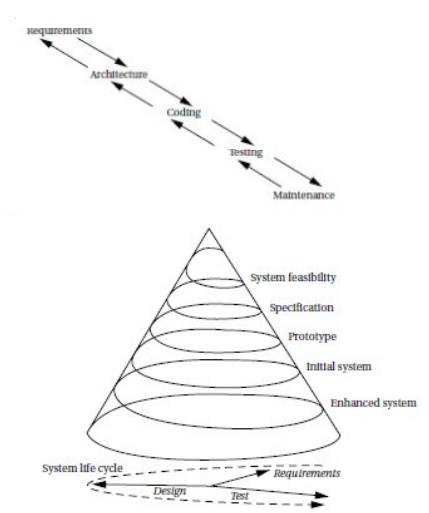
Above
Figure illustrates an alternative model of software development called the spiral model While the waterfall model
assumes that the system is built once in its entirety, the spiral model assumes
that several versions of the system Successive
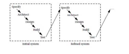
refinement design methodology.
In this approach, the system is built several
times.
A first system is used as a rough prototype, and
successive models of the system are further refined. This methodology makes
sense when you are relatively unfamiliar with the application domain for which
you are building the system.
Refining the system by building several
increasingly complex systems allows you to test out architecture and design
techniques.
The
various iterations may also be only partially completed;for example,continuing
an initial system only through the detailed design phase may teach you enough
to help you avoid many mistakes in a second design iteration that is carried
through to completion.
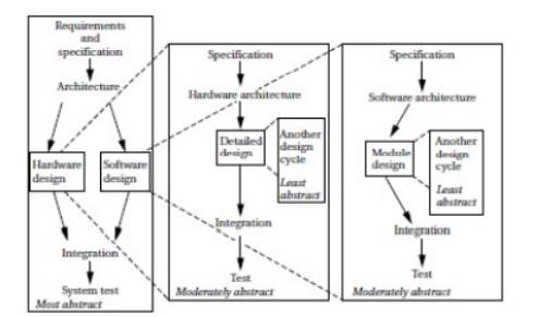
Embedded computing systems often involve the design
of hardware as wellas software.
Even if you aren’t designing a board, you may be
selecting boards and plugging together multiple hardware components as well as
writing code
Concurrent engineering
Concurrent
engineering attempts to take a broaderapproach and optimize the
total flow.
Reduced design time is an important goal for
concurrent engineering, but it can help with any aspect of the design that cuts
across the design flow, such as reliability, performance, power consumption,
and so on.
It tries to eliminate “over-the-wall” design steps, in which one designer
performs
an isolated task and then throws the result over the wall to the next designer,
with little interaction between the two.
In particular, reaping the most benefits from
concurrent engineering usually requires eliminating thewall between design and
manufacturing.
Concurrent
engineering efforts are comprised of several elements:
■
Cross-functional
teams include members from various disciplines involved in the process, including manufacturing, hardware and
software design, marketing, and so forth.
■
Concurrent
product realization process activities are at the heart of concurrent
engineering. Doing several things at
once, such as designing various subsystems simultaneously, is critical to
reducing design time.
■
Incremental
information sharing and use helps minimize the chance that concurrent
product realization will lead to
surprises. As soon as new information becomes available, it is shared and
integrated into the design. Cross functional teams are important to the
effective sharing of information in a timely fashion.
■
Integrated
project management ensures that someone is responsible for the entire
project, and that responsibility is
not abdicated once one aspect of the work is done.
Early and continual supplier involvement helps
make the best use of suppliers’ capabilities.
■
Early and
continual customer focus helps ensure that the product best meets customers’
needs.
REQUIREMENTS ANALYSIS
Requirements
are
informal descriptions of what the customer wants, while specifications are more
detailed, precise, and consistent descriptions of the system that can be used
to create the architecture.
Both requirements and specifications are, however,
directed to the outward behavior of the system, not its internal structure. The
overall goal of creating a requirements document is effective communication
between the customers and the designer
A good
set of requirements should meet several tests:
■ Correctness: The requirements should not
mistakenly describe what the customer wants. Part of correctness is avoiding
over-requiring—the requirements should not add conditions that are not really
necessary.
Unambiguousness: The requirements document should
be clear and have only one plain language
interpretation.
■
Completeness:
All
requirements should be included.
■
Verifiability:
There
should be a cost-effective way to ensure that each requirement is satisfied in the final product. For example, a
requirement that the system package be “attractive” would be hard to verify
without some agreed upon definition of attractiveness
■
Consistency:
One
requirement should not contradict another requirement.
■
Modifiability:
The
requirements document should be structured so that it can be modified to meet changing requirements without
losing consistency, verifiability, and so forth.
■
Traceability:
Each
requirement should be traceable in the following ways:
We should be able to trace backward from the
requirements to know why each requirement exists.
We should also be able to trace forward from
documents created before the requirements
(e.g.,
marketing memos) to understand how they relate to the final requirements.
We should be able to trace forward to understand
how each requirement is satisfied in the implementation.
We should also be able to trace backward fromthe
implementation to know which requirements they were intended to satisfy.
SPECIFICATIONS
Control-Oriented Specification Languages
We have already seen how to use state machines to
specify control in UML.
An example of a widely used state machine
specification language is the SDL
language
SDL specifications include states, actions, and
both conditional and unconditional transitions between states. SDL is an
event-oriented state
Statechart
The Statechart
is one well-known technique for state-based specification that introduced some
important concepts.
The Statechart notation uses an event-driven model
Statecharts
allow states to be grouped together to show common functionality.
There are
two basic groupings:
OR and
AND
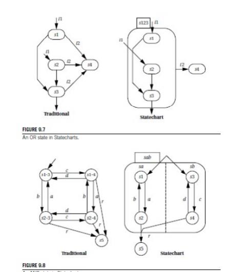
the AND/OR
table, to describe similar relationships between states. An example AND/OR
table and the Boolean expression it describes are shown in Figure.
SYSTEM ANALYSIS AND ARCHITECTURE DESIGN
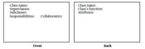
The CRC card
methodology is a well-known and useful way to help analyze a system’s
structure.
It is particularly well suited to object-oriented
design since it encourages the encapsulation of data and functions
The acronym CRC
stands for the following three major items that the methodology tries to
identify:
■ Classes define the logical groupings of
data and functionality.
■
Responsibilities
describe
what the classes do.
■
Collaborators
are the
other classes with which a given class works
The name CRC card comes from the fact that the
methodology is practiced by having people write on index cards. (In the United
States,the standard size for index cards is 3”x5”inches), An example card is
shown in Figure
The
walkthrough process used with CRC cards is very useful in scoping out a design
and determining what parts of a system are poorly understood.
This
informal technique is valuable to tool-based design and coding following steps
are followedwhen using it to analyze a system:
Develop
an initial list of classes: Write down the class name and perhaps
a few words on what it does.
Write an
initial list of responsibilities and collaborators: The
responsibilities list helps describe
in a little more detail what the class does
Create
some usage scenarios: These scenarios describe what the system does.
Walk
through the scenarios: This is the heart of the methodology. During the
walkthrough, each person on the team
represents one or more classes.
Refine
the classes, responsibilities, and collaborators: Some of
this will be done during the course
of the walkthrough, but making a second pass after the scenarios is a good idea
Add class
relationships: Once the CRC cards have been refined, subclass and
superclass relationships should
become clearer and can be added to the cards.
QUALITY ASSURANCE
The quality assurance (QA) process is vital
for the delivery of a satisfactory system.
QUALITY ASSURANCE TECHNIQUES
The
International Standards Organization (ISO) has created a set of quality
standards known as
ISO 9000.
ISO 9000 was created to apply to a broad range of
industries, including but not limited to embedded hardware and software.
A standard developed for a particular product, such
as wooden construction beams, could specify criteria particular to that
product, such as the load that a beam must be able to carry.
However, a wide-ranging standard such as ISO 9000
cannot specify the detailed standards for every industry.
Related Topics