Chapter: Electric Energy Generation and Utilisation and Conservation : Electric Drives and Traction
Electric braking
Braking:
Braking is very frequent in electric drives to stop a motor in a reasonably short time.
For example a plannar must quickly be stopped at the end of its stroke and sometimes must quickly be stopped at the end of its stroke and sometimes it is necessary to stop the motor in order to prevent accident
The essential of a good braking system should be
1) Reliable and quick in its action.
2) The braking force must be capable of being controlled.
3) Adequate means be provided for dissipating the stored energy that is kinetic energy of the rotating parts.
4) In case of a fault in any part of the braking system the whole system must come to instantaneous rest or result in the application of the brakes.
There are two types of braking:
1) Mechanical braking:
The motor in this case is stopped due to friction between the moving part of the motor and the brake shoe that is stored energy is dissipated as heat by a brake shoe or brake lining which rubs against a brake shoe or brake lining which rubs against a brake drum.
2) Electric braking:
In this method of braking, the kinetic energy of the moving parts that is motor is converted into electrical energy which is consumed in a resistance as heat or alternatively it is returned to the supply source.
During braking operation a motor has to function as a generator.
The motor can be held at stand still. In other words the electric braking cannot hold the motor at rest.
Thus it becomes essential to provide mechanical brakes in addition to electric braking.
Electric braking:
Various types of electrical braking are:
a) Plugging
b) Rheostatic braking
c) Regenerative braking
a. Plugging :
This is a simple method of electric braking and consists in reversing the connections of the armature of the motor so as to reverse its direction of rotation which will oppose the original direction of rotation of the motor and will bring it to zero speed when mechanical brakes can be applied.
At the end of the braking period the supply to the motor is automatically cut off. This method of braking can be applied to the following motors.
1) DC motors
2) Induction motors
3) Synchronous motors
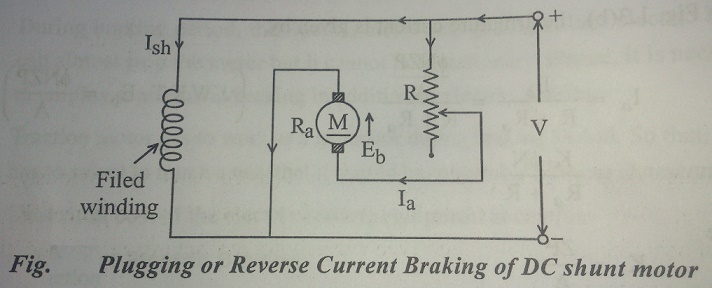
Plugging applied to DC motors:
To reverse a DC motors, it is necessary to reverse the connections of the armature while the connections of the field are kept the same.
The direction of m.m.f remains the same even during braking periods.
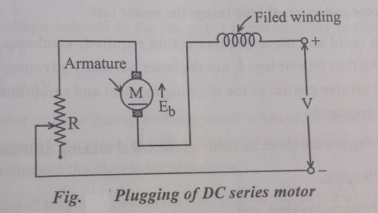
Series motors:
Total voltage of V+ Eb is available across the armature terminals which causes a current I to flow around the circuit.
When Eb = V then the voltage across the armature is 2V and at the time of braking twice the normal voltage is applied to the resistance in series with the armature at this time in order to limit the current.
While the motor is being braked, the current is still being drawn from the supply.
This method requires energy from the supply for its action and not only the kinetic energy of the motor is being wasted, but this energy is also being dissipated. Speed and braking torque Electric braking to torque
TB α ФI---------------------------- (1)
TB = K ФI ---------------------------- (2)
Where K is a constant
Current = V+ Eb/ R-------------------- (3)
Eb= K1N Ф--------------------- (4)
N is the speed
K1 is a constant
Substitute the value of Eb from equation (4) in (3)
Current I = (V + K1N Ф)/ R -------------------- (5)
In view of equations (2) and (5)
TB = K Ф[(V + K1N Ф)/ R]
= K ФV/ R + KK1N Ф2/ R
= K2 Ф + K3 Ф2N --------------------- (6)
Where K2 = KV/ R -------------------- (7)
And K3 = KK1/R--------------------- (8)
Apply the results obtained to the series motor, where
Ф α armature current (Ia)------------------- (9)
Then Electric braking in series motor,
= K4 Ia + K5 Ia2-------------------- (10)
In the case of shunt motor since flux is constant
Electric braking torque:
Wherever there is a load on the machine the load will also exert braking torque due to it and then the total braking torque (T)
T = Electric braking torque + Load torque ---------------- (12)
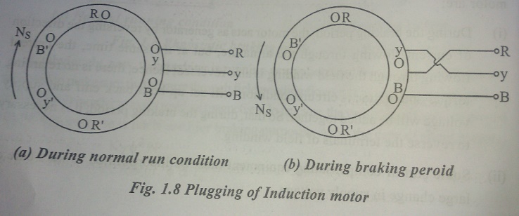
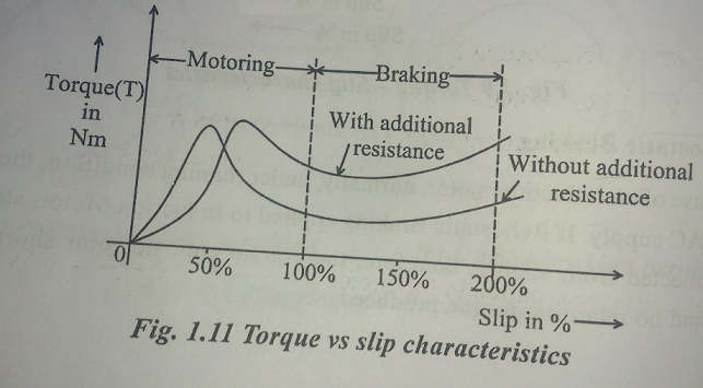
Plugging applied to induction motors:
In the case of induction motor its speed can be reversed by inter changing any of the two stator phases which reverses the direction of rotation of motor field.
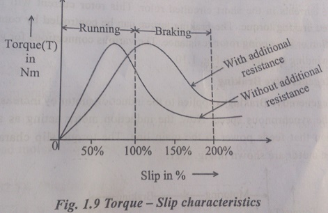
Actually at the time of braking when the induction motor is running at near synchronous speed.
The point Q represents the torque at the instant of plugging one can notice that the torque increases gradually as one approaches the stand still speed.
Different values of rotor resistance give rise to different shapes of speed torque curve in order to
give any desired braking effect.
The rotor current I2 can be calculated during the braking period from the following
relation and is plotted as shown.
I2 = SE2/ √ [Re2 + (SX2)2] ------------------- (13)
Where E2 is the e.m.f. induced in rotor at standstill
R2 is the rotor resistance
X2 is the standstill reactance of the rotor and
S2 is the percentage slip
Plugging applied to synchronous motors
Plugging can be applied to the synchronous motors, with the only difference that the field on the rotor will be rotating in opposite direction to that of the rotating field on the stator with the synchronous speed and the relative velocity between the two will be twice the synchronous speed.
b. Rheostatic braking
In this method of braking, the motor is disconnected from the supply and run as generator driven by the remaining kinetic energy of the equipment that is the energy stored in motor and load which are to be braked.
The following drives can be braked by the rheostatic method:
1) DC motor
2) Induction motor
3) Synchronous motor
Dc motors
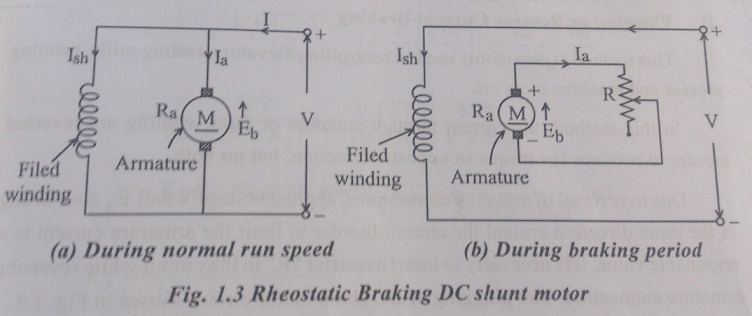
Shunt motor:
In this type of motor, the armature is simply disconnected from the supply and is connected to as resistance in series with it, the field; winding remains connect to the supply.
The braking can be adjusted suitably by varying the resistance in the armature circuit.
In the case of failure of the supply, there is no braking torque because of absence of the field.
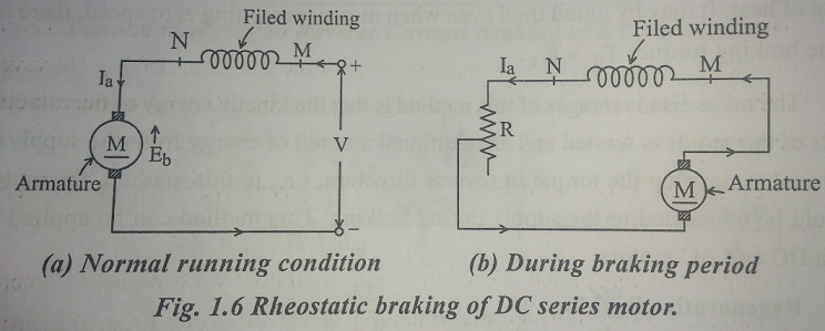
Series motor:
In this case of the connections are made as shown is fig during braking operation.
The motor after disconnection from the supply in made to run as a DC series generator.
Braking torque and speed
Electric braking torque is given by equation (3)
Braking current = Eb/ R---------------------------------- (14)
Hence braking current of equation (14) and (4)
= K1ФN/R ---------------------------------- (15)
Substitute the value of braking current is equation (1)
Electric braking torque = KK1Ф2N/R
= K2 Ф2N --------------------------------- (16)
Where K2 = KK1/R-------------------------------- (17)
In the case of a series motor the flux dependent upon the armature current
Electric braking torque for series motor
= K3Ia2N-------------------------------- (18)
While in the case of shunt motor since flux is constant
Electric braking torque = K4N------------------------------- (19)
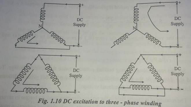
Rheostatic braking is applied to induction motor:
In this case the stator is disconnected from the supply and is connected to DC supply which excites the windings thereby producing a DC field.
The rotor is short-circuited across through resistance in each phase.
When the short circuited rotor moves it outs the steady flux produced in the air gap due to DC current flowing in the stator produced in the air gap due to DC current flowing in the stator and an e.m.f is induced in the rotor conductors Rheostatic braking in the synchronous motors is similar to the rheostatic braking in induction motors.
In this case the stator is shorted across resistance in star or delta and the machine works like an alternator supplying the current to the resistance, there by dissipating in kinetic energy in the form of losses in the resistances.
c. Regenerative braking:
In this type of braking the motor is not disconnected from the supply but remains connected to it and its feeds back the braking energy or its kinetic energy to the supply system.
This method is better than the first and second methods of braking since no energy is wasted and rather it is supplied back to the system.
This method is applicable to following motors:
1) D.C motors
2) Induction motors
D.C motors:
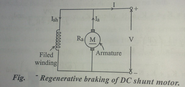
Shunt motor:
In a DC machine where energy will be taken from the supply or delivered to it depends upon the induced emf, if it in less than the line voltage the machine will operate as motor and if it is more than the line voltage, the machine will operate as generator.
The e.m.f induced in turn depends upon the speed and excitation that is when the field current or the speed is increased the induced e.m.f exceeds the line voltage and the energy will be field into the system.
This will quickly decrease the speed of the motor and will bring it to rest.
Series motor:
In this case, complications arise due to fact that the reversal of the current in the armature would cause a reversal of polarity of the series field.
In the case of induction motors, the regenerative braking is inherent, since an induction motor act as a generator when running at speeds above synchronous speeds and it feeds power back to the supply system.
No extra auxiliaries are needed for this purpose.
This method is however very seldom used for braking but its application is very useful to lifts and hoists for holding a descending load at a speed only slightly above the synchronous speed.
Tramways:
The tramway is perhaps the cheapest type of transport available in very dense traffic.
It receives power through a bow collector or a grooved wheel from an overhead conductor at about 600 V D.C., the running rail forming the return conductor.
It is provided with atleast two driving axles in order to secure necessary adhesion, start it from either end and use two motors with series- parallel control.
Two drum-type controllers, one at each end used for controlling the tramcar.
Though these controllers are connected in parallel, they have suitable interlocking arrangement to prevent their being used simultaneously.
The main frame of the car body is made from high tensile steel. Aluminium is extensively used for bodywork.
The under frame is of rolled steel sections. Seats are either in transverse direction or a combination of transverse and longitudinal arrangement is used.
The equipment is similar to that used in railways but the output is considerably smaller and does not exceed 60 to 75 H.P.
For normal service rheostatic and mechanical braking are employed.
For mechanical braking, electro-mechanical drum brakes are used. Also magnetic tracks brakes are used for giving better retardation.
Trolley-Bus:
Serious drawback of tramway is the lack of manoeuvrability in congested areas and noise; this is overcome by the trolley-bus drive.
It is an electrically- operated pneumatic-tyred vehicle which needs no track in the roadway. It receives its power at 600 V D.C. from two overhead contact wires.
A D.C compound motor of output of 50 to 100 kW is normally used.
Speed control is obtained by field weakening method. Foot operated master controllers are used so that drive may have his hands free to steer the vehicle and apply hand brake. One pedal controls the starting, speed control and regenerative braking, if any and second pedal control rheostatic and compressed air brakes. Regenerative braking is usually not employed in trolley-bus drive because of difficulty of ensuring that supply system is always in a position to absorb the energy regenerated.
The lighting system in the car is low-voltage D.C supplied from a motor- generator set connected in parallel with a battery. The vehicles are usually provided with secondary batteries so that the vehicles can be manoeuvred in case of emergency.
Since the body of the car is insulated from earth on account of the rubber-tyred wheels, it must be properly checked for adequate insulation resistance lest it leaks and causes electric shocks to the passengers while boarding and alighting from the bus. The insulation resistance is checked at the end of the day.
Trolley – buses have more passenger carrying capacity, higher acceleration and braking retardation than oil-engined buses. These are, therefore, used for medium traffic density as obtained in inner suburbs. Oil engine buses, on the other hand, are used for outer suburbs and country side where there is low traffic density.
Related Topics